Thursday, May 29. 2014
Radseed: A Kernel Module for Real Randomness
Wednesday, May 14. 2014
Interfacing Cirrus Logic Audio ADCs
I've been considering ideas for audio gear of various sorts over the past few months, and decided a good starting place would be a solid ADC interface from which I could prototype concepts. Lots of companies make audio converters, but I settled on two models from Cirrus Logic: the CS5361 and CS5340. They are, respectively, balanced and unbalanced two-channel 24-bit 192 khz high dynamic range delta-sigma oversampling devices.
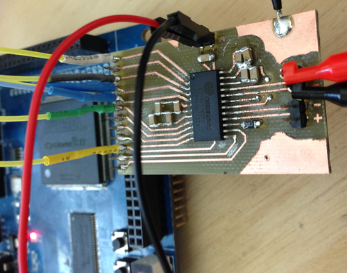
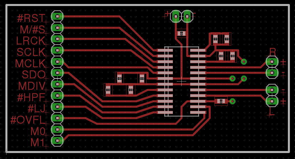
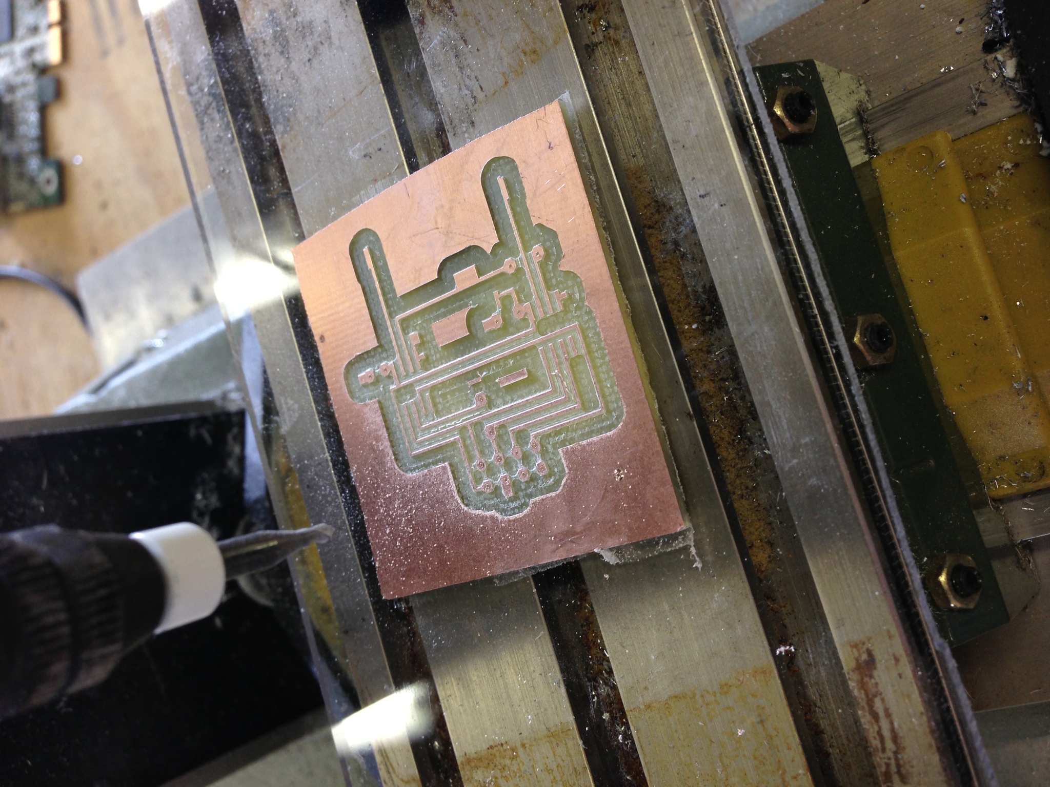
I started by laying out a super-simple protoboard for the CS5361. Since I wanted this to be quick and easy to cut on the CNC mill, the board is single-sided with the bare minimum of filtering, and without standard mixed signal board design concepts like separate analog and digital ground planes. While this will negatively affect the noise figure a bit, I wanted to get the device up and running with the minimum investment of time in case my assumptions regarding its usage and support were incorrect.

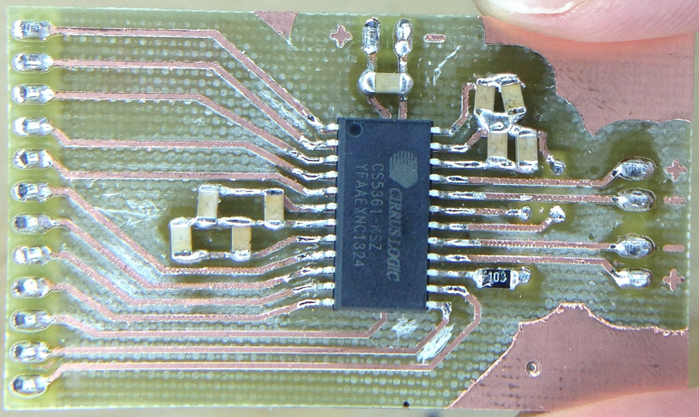
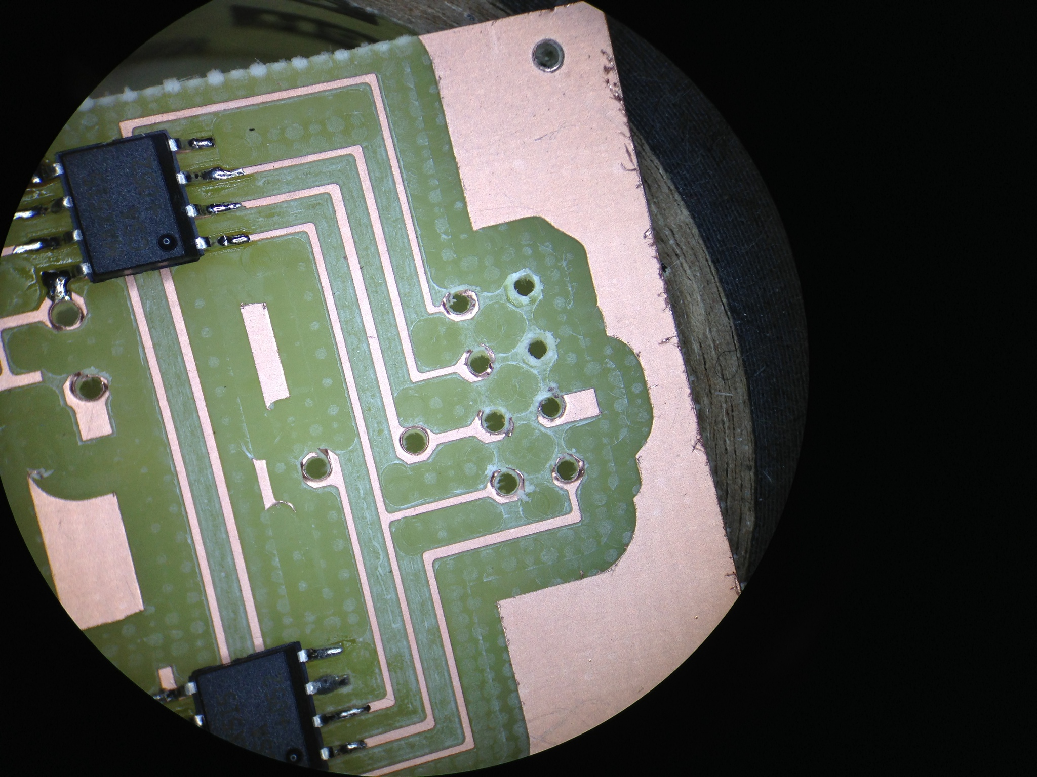
By the time I had finished the layout and cut the board, the samples order had arrived! Soldering was quick though a tad arduous - I need to use a larger 1206 footprint next time.

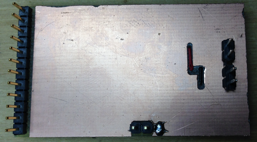
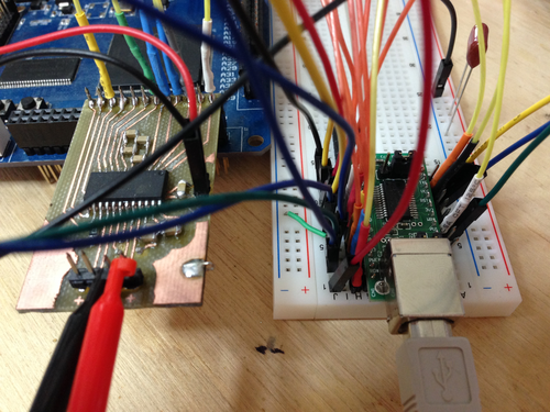
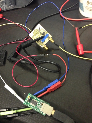
My ugly solder job notwithstanding, I plugged the unit into a breadboard, wired up an oscillator, config pins, and the logic analyzer, and was immediately rewarded with correct operation:
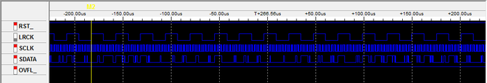
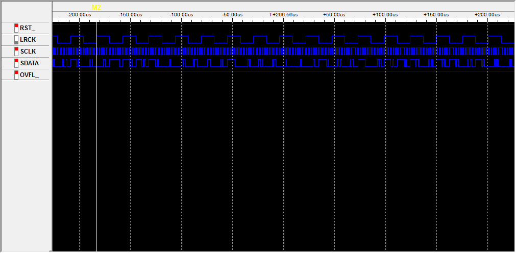
In short, by simply applying power, config pin states, and a master clock, the device will shift out ADC values (in 2's compliment form) msb-first on the falling edge of SCLK (ie, we sample on the rising edge):

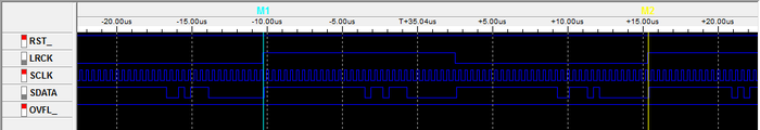
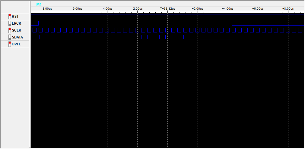
The only other line we need to worry about is LRCK, which indicates the channel being sent - you can see here that we get a left sample, then a right sample, then repeat:
With the hardware working, I set about writing the Verilog modules to nab samples from the ADC and send them off via USB (using an FT245R FIFO interface I have on hand). The code is extremely simple: on the rising edge of SCLK, samples are shifted into an 8-bit register - the size of the data bus on the USB interface. Every 8 bits, that register is strobed into the FT245R and the process repeats.
Byte alignment is provided by LRCK: on a start or reset condition from the USB host, the FPGA waits for a rising edge of LRCK before beginning the sampling and transmission of samples. This allows the client end to interpret the data stream without framing bytes: incoming data is simply shifted into 3-byte (24-bit) samples, left then right, and processed as desired.
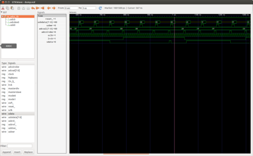
The code was quick to write and simulate with my favorite tools, iVerilog and GTKWave. I implemented a quick CS5361 module whose left and right channels count up and down (respectively) so as to simulate the rest of the pieces. Unfortunately I spent almost as much time debugging the code in hardware with the logic analyzer as I did writing the code, as Quartus (the Altera design software) is rather inconsistent in its handling of constants and register widths. (note: always read every line of output from the Altera synthesis toolchain - one can easily spend 4 hours trying to debug a problem that makes no sense only to find that the synthesis tool decided a constant was the wrong size and used zero instead)
In any event, I did manage to squash the few Quartus oddities that had caused the hardware to operate differently from the simulated code, and verified that the USB interface looked correct using the logic analyzer. Time for more spaghetti:
Time to test it out. In its current state, the FPGA will assert a reset condition on any received byte from the FIFO buffer. So, we will send a reset byte then read 24 samples of 6 bytes (3 for each channel):
root@ichor ~ # echo -n 0 > /dev/ttyUSB0 && dd if=/dev/ttyUSB0 count=24 bs=6 2>/dev/null | hexdump
0000000 3238 a13f 4a68 a650 0344 bd41 6632 ceaa
0000010 78f2 28f8 9764 19ca 7185 45b4 6bfd eabf
0000020 9825 8050 65e5 6122 3adc 0830 28f0 9dfc
0000030 d026 746a e2c0 befa 57dc 1fa4 4225 7b82
0000040 a61b ed00 2320 d641 e111 b648 a2f3 8d3a
0000050 bdfb afb6 1287 5963 ff57 9c8e 63a1 3971
0000060 4bfe ac6e 5081 9fae 2b0d 5c4c 6eaa 26b7
0000070 164b 6093 8378 96d8 138c 160e e661 a81b
0000080 81bc bdae 530b ec79 3537 6ada b0cc 4773
0000090
Success! With that working, the next steps are to implement the CS5340 and add proper dynamic configuration loading. From there, I am hoping to implement ADAT input and output and a simple device driver to interface the kernel audio subsystem.
I've put the code, board design, and a bit of documentation on GitHub: jackcarrozzo/cs_adcs.
I started by laying out a super-simple protoboard for the CS5361. Since I wanted this to be quick and easy to cut on the CNC mill, the board is single-sided with the bare minimum of filtering, and without standard mixed signal board design concepts like separate analog and digital ground planes. While this will negatively affect the noise figure a bit, I wanted to get the device up and running with the minimum investment of time in case my assumptions regarding its usage and support were incorrect.
By the time I had finished the layout and cut the board, the samples order had arrived! Soldering was quick though a tad arduous - I need to use a larger 1206 footprint next time.

My ugly solder job notwithstanding, I plugged the unit into a breadboard, wired up an oscillator, config pins, and the logic analyzer, and was immediately rewarded with correct operation:
In short, by simply applying power, config pin states, and a master clock, the device will shift out ADC values (in 2's compliment form) msb-first on the falling edge of SCLK (ie, we sample on the rising edge):
The only other line we need to worry about is LRCK, which indicates the channel being sent - you can see here that we get a left sample, then a right sample, then repeat:

With the hardware working, I set about writing the Verilog modules to nab samples from the ADC and send them off via USB (using an FT245R FIFO interface I have on hand). The code is extremely simple: on the rising edge of SCLK, samples are shifted into an 8-bit register - the size of the data bus on the USB interface. Every 8 bits, that register is strobed into the FT245R and the process repeats.
Byte alignment is provided by LRCK: on a start or reset condition from the USB host, the FPGA waits for a rising edge of LRCK before beginning the sampling and transmission of samples. This allows the client end to interpret the data stream without framing bytes: incoming data is simply shifted into 3-byte (24-bit) samples, left then right, and processed as desired.

The code was quick to write and simulate with my favorite tools, iVerilog and GTKWave. I implemented a quick CS5361 module whose left and right channels count up and down (respectively) so as to simulate the rest of the pieces. Unfortunately I spent almost as much time debugging the code in hardware with the logic analyzer as I did writing the code, as Quartus (the Altera design software) is rather inconsistent in its handling of constants and register widths. (note: always read every line of output from the Altera synthesis toolchain - one can easily spend 4 hours trying to debug a problem that makes no sense only to find that the synthesis tool decided a constant was the wrong size and used zero instead)

In any event, I did manage to squash the few Quartus oddities that had caused the hardware to operate differently from the simulated code, and verified that the USB interface looked correct using the logic analyzer. Time for more spaghetti:

Time to test it out. In its current state, the FPGA will assert a reset condition on any received byte from the FIFO buffer. So, we will send a reset byte then read 24 samples of 6 bytes (3 for each channel):
root@ichor ~ # echo -n 0 > /dev/ttyUSB0 && dd if=/dev/ttyUSB0 count=24 bs=6 2>/dev/null | hexdump
0000000 3238 a13f 4a68 a650 0344 bd41 6632 ceaa
0000010 78f2 28f8 9764 19ca 7185 45b4 6bfd eabf
0000020 9825 8050 65e5 6122 3adc 0830 28f0 9dfc
0000030 d026 746a e2c0 befa 57dc 1fa4 4225 7b82
0000040 a61b ed00 2320 d641 e111 b648 a2f3 8d3a
0000050 bdfb afb6 1287 5963 ff57 9c8e 63a1 3971
0000060 4bfe ac6e 5081 9fae 2b0d 5c4c 6eaa 26b7
0000070 164b 6093 8378 96d8 138c 160e e661 a81b
0000080 81bc bdae 530b ec79 3537 6ada b0cc 4773
0000090
Success! With that working, the next steps are to implement the CS5340 and add proper dynamic configuration loading. From there, I am hoping to implement ADAT input and output and a simple device driver to interface the kernel audio subsystem.
I've put the code, board design, and a bit of documentation on GitHub: jackcarrozzo/cs_adcs.
Monday, April 21. 2014
Adventures in Linux on Sun Netra T1
Thursday, February 20. 2014
WWVB Receiver and Testing Transmitter
As I've been making steady progress on my Z80 computer, I've put a lot of thought into something to actually do with it when it's done. As tempting as it is to load up CP/M, add a video interface, and use it as my main machine, I think porting Firefox is too ambitious. For now, I've decided to add some more 7-segment displays and an RF front end to decode the WWVB time signal from an atomic clock in Colorado and hang it on the wall. If I'm still feeling ambitious, I'll add an Ethernet controller and write a driver and NTP daemon for it. Of course, this means I need a working receiver front end for 60kHz.

The WWVB signal is quite simple as far as decoding goes: the carrier has "full power" and "low power" states. The transmitter drops the carrier by 17 dB at the start of each second, and the length of time before it returns provides a single trinary value: Mark (0.8s), Not Set (0.2s), or Set (0.5s). A single digital line that goes low or high to follow the transmitter power state is quite easy to achieve with a fully analog circuit: after a bandpass to select only the 60kHz carrier, we send the signal into two peak detectors - one with a long time constant (low pass filter) to track the average signal power over several seconds, and one with a shorter time constant to track the per-second changes. Passing these two signals to a comparator, we get our nice single-bit TTL indicator of the current signal state. Plus, the longer time constant peak detector acts as an auto gain control, so no alignment is required.

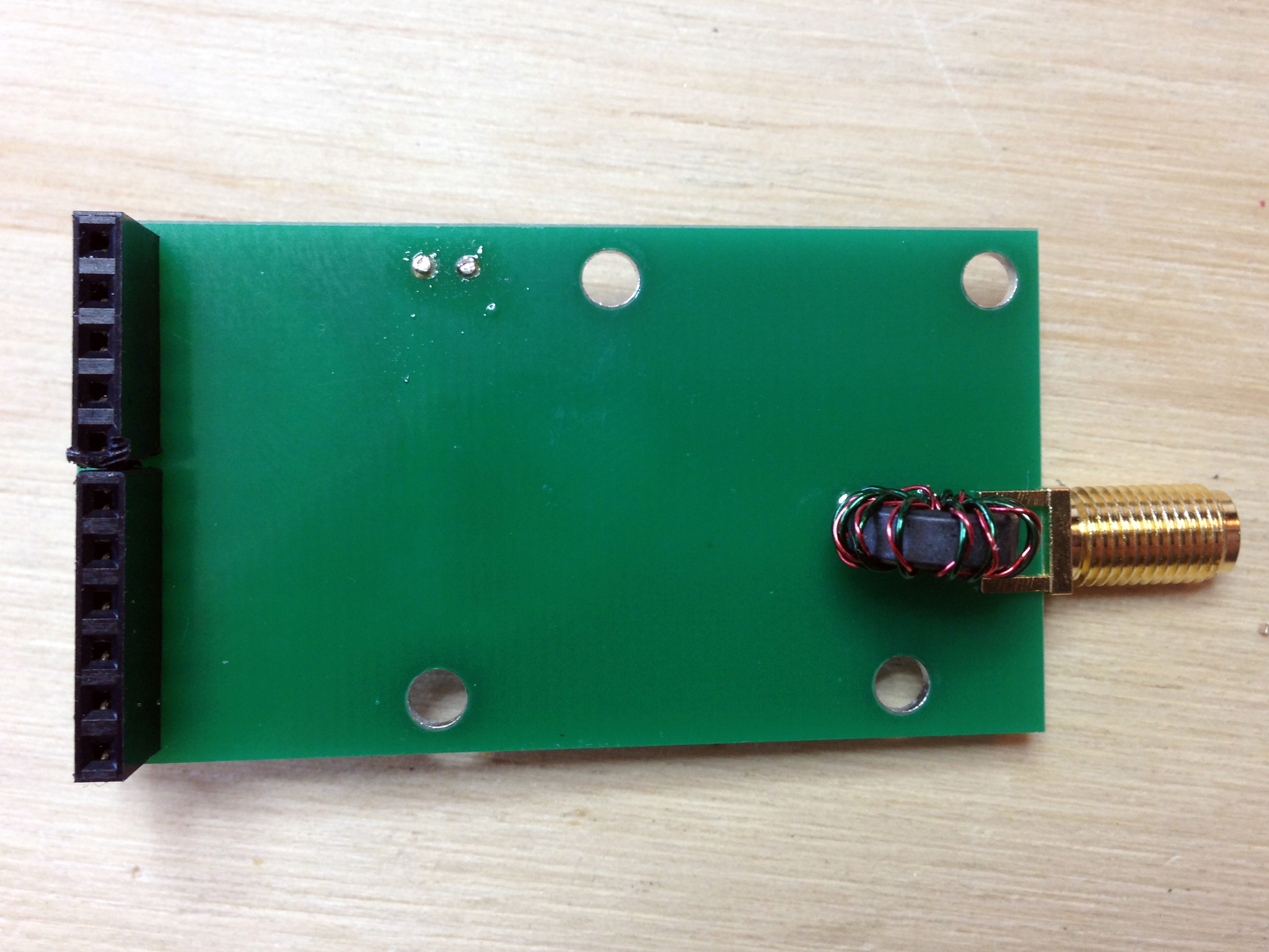
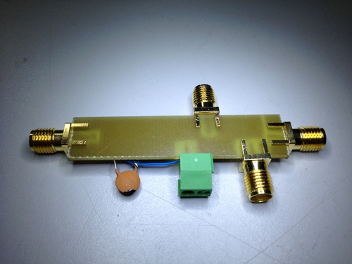
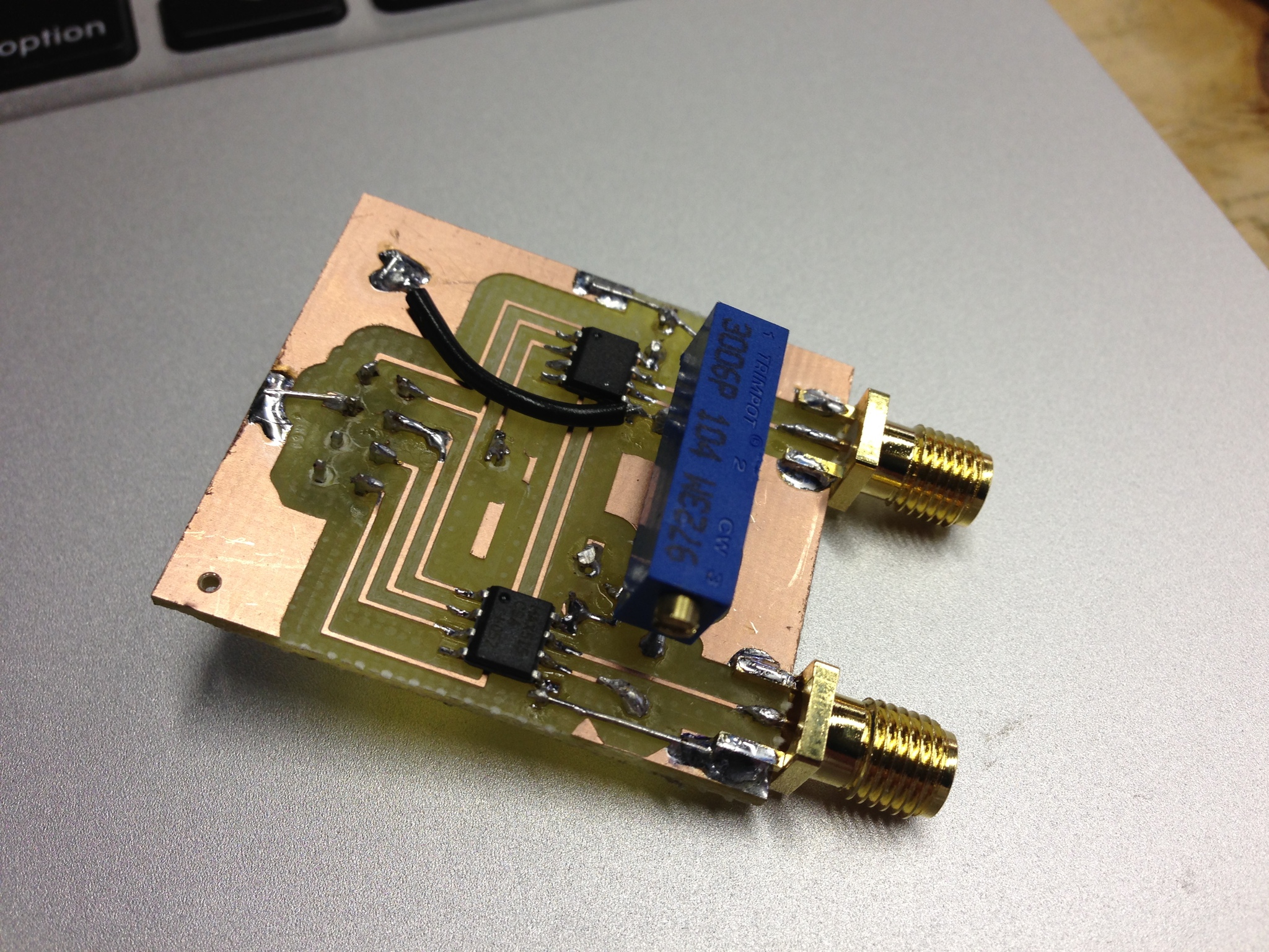
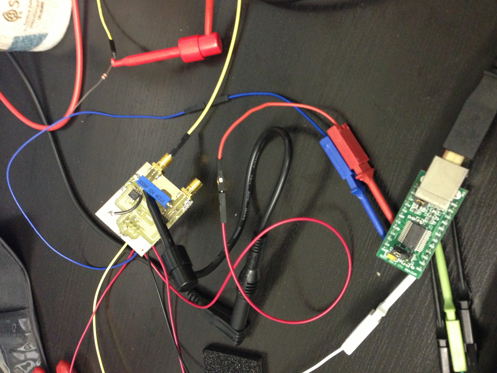
While I will make my own receiver as described above for the final version, I ordered a SYM-RFT module for testing. It includes an LED to indicate received carrier status and outputs the inverted carrier power state compared to the average carrier power. I quickly breadboarded it up to an FT245R USB chip and wrote a few lines of C to poll the power status and measure the length of state changes. Unfortunately, New England being quite far from Colorado, the signal is below the noise floor and has thus far been highly unreliable. The module simply flashes chaotically in the presence of any electronic noise like my monitors, and does nothing in isolation.
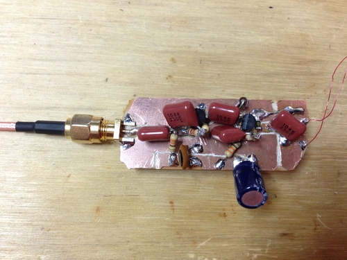
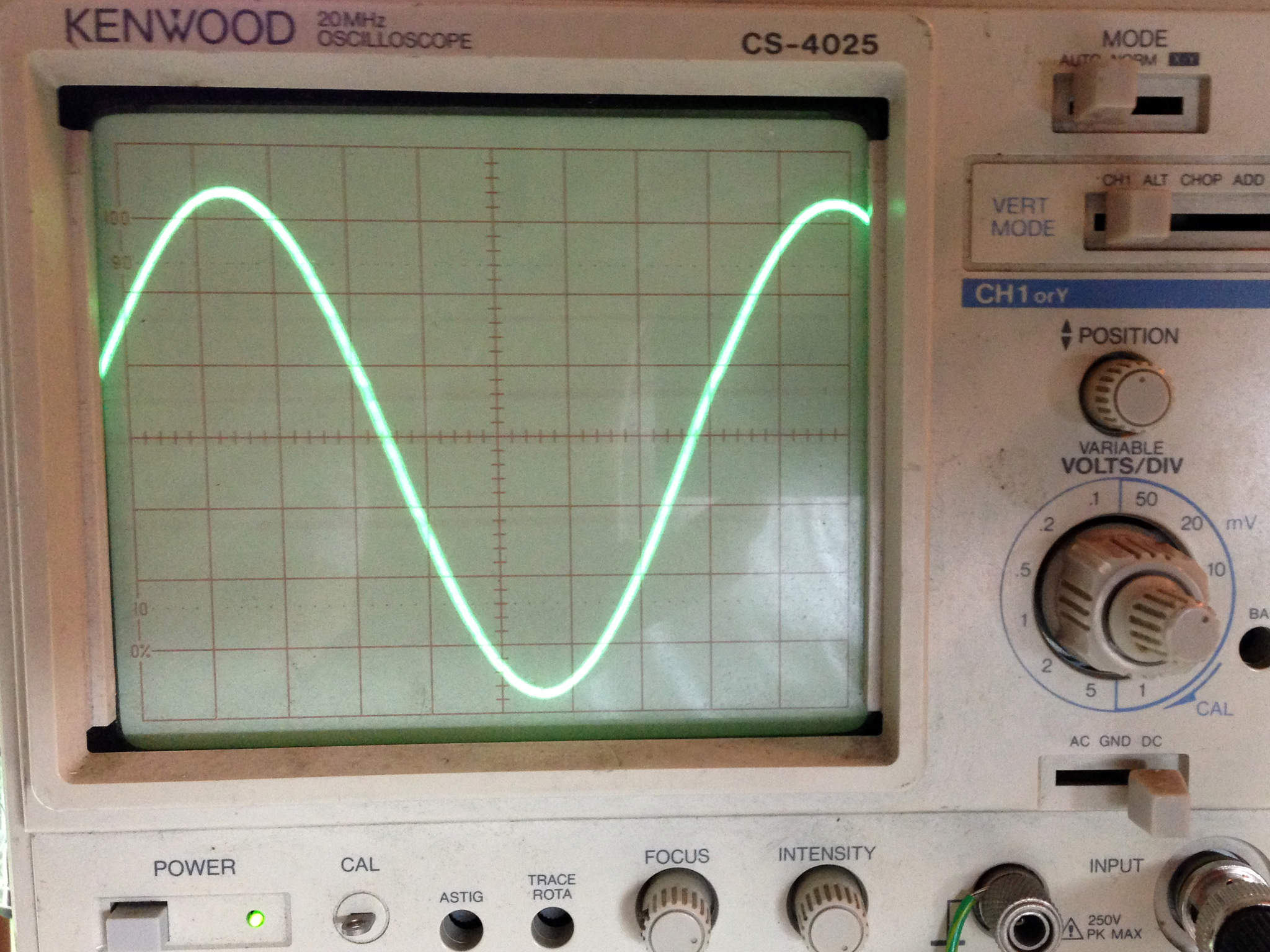
I built the above two-stage preamp from two 2N3904's to attach to the 60kHz antenna that came with the SYM-RFT module to see if I could see any carrier on the oscilloscope. While I did get all sorts of noise and impulses, there was very little if any energy at 60kHz. Drat.
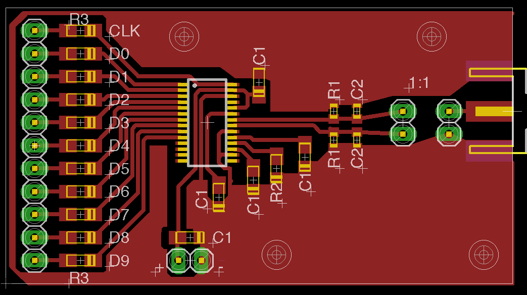
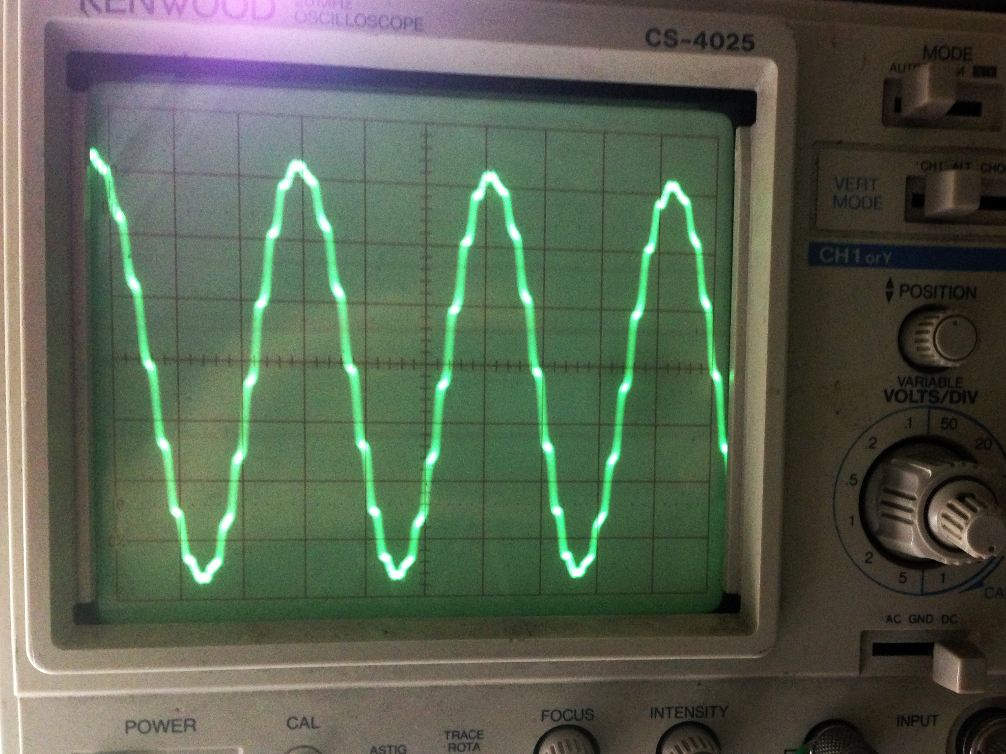
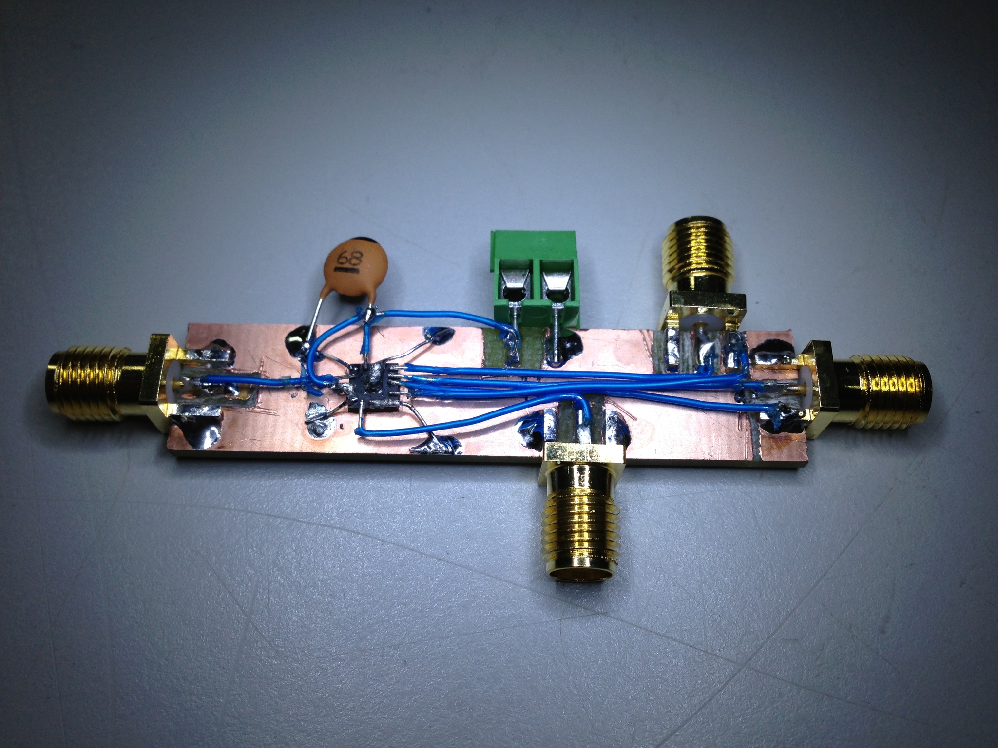
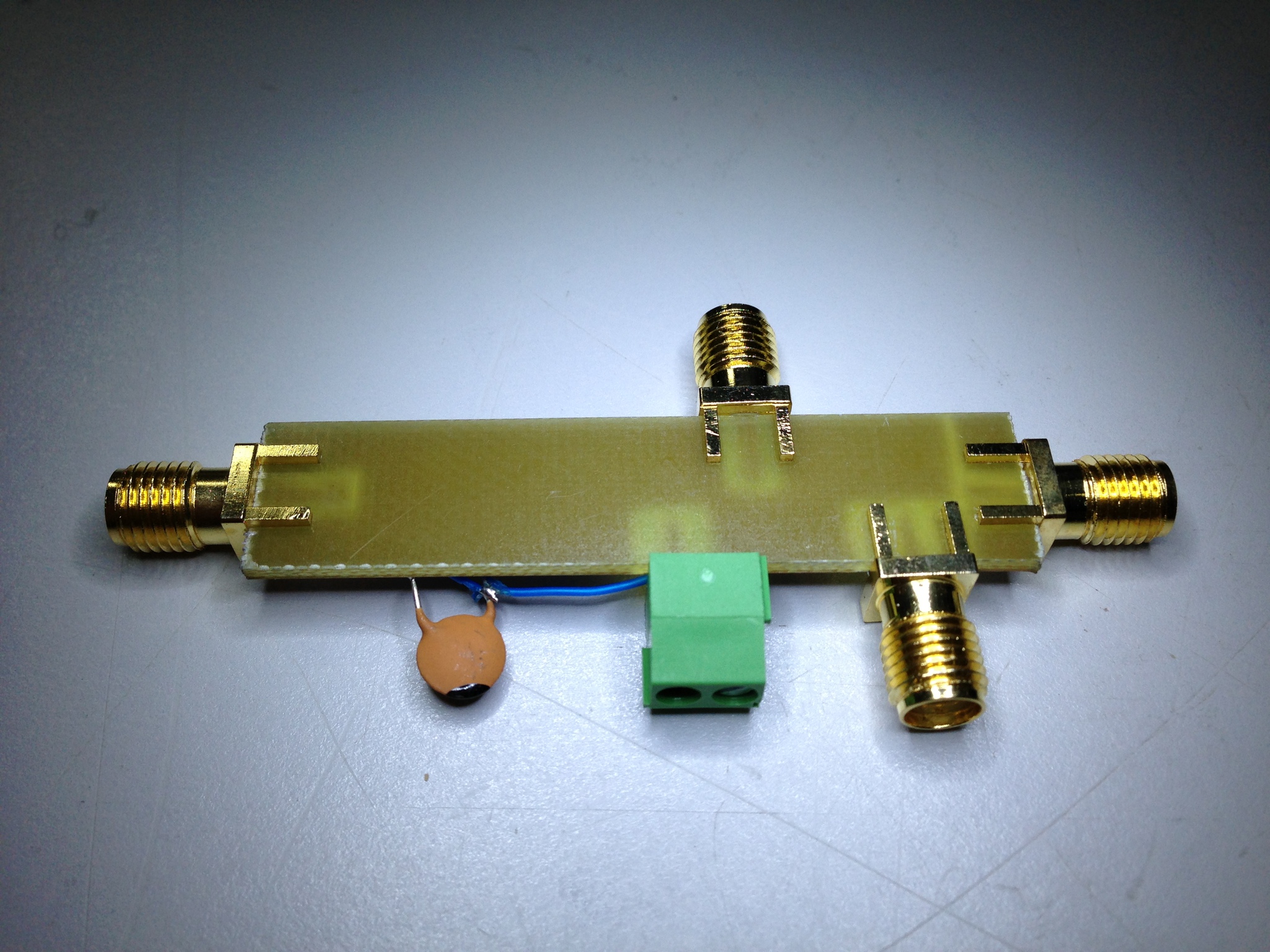
Luckily, I have the tools on hand to recreate the signal so I can at least test my receiver and code. I pulled out the FPGA RF DAC board I put together a while back, and a page of Verilog later I had a compliant WWVB transmitter:
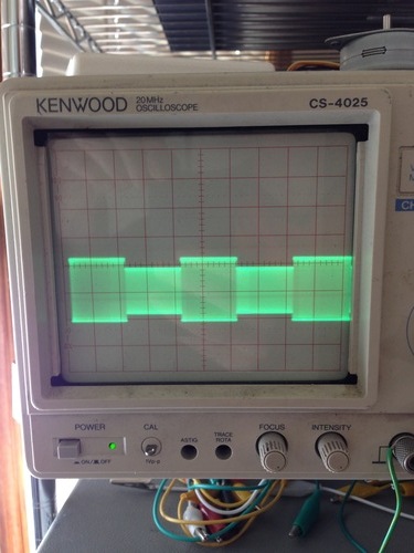
After a small battle with PLLs to get a slow enough clock for 60khz, both the SYM-RFT and my USB worked fine.
jackc@ichor ~/Projects/wwvb_usb $ sudo ./wwvb
MARK : 950 ms
NOT SET : 239 ms
SET : 503 ms
NOT SET : 194 ms
SET : 581 ms
MARK : 991 ms
^Cjackc@ichor ~/Projects/wwvb_usb $
The WWVB signal is quite simple as far as decoding goes: the carrier has "full power" and "low power" states. The transmitter drops the carrier by 17 dB at the start of each second, and the length of time before it returns provides a single trinary value: Mark (0.8s), Not Set (0.2s), or Set (0.5s). A single digital line that goes low or high to follow the transmitter power state is quite easy to achieve with a fully analog circuit: after a bandpass to select only the 60kHz carrier, we send the signal into two peak detectors - one with a long time constant (low pass filter) to track the average signal power over several seconds, and one with a shorter time constant to track the per-second changes. Passing these two signals to a comparator, we get our nice single-bit TTL indicator of the current signal state. Plus, the longer time constant peak detector acts as an auto gain control, so no alignment is required.
While I will make my own receiver as described above for the final version, I ordered a SYM-RFT module for testing. It includes an LED to indicate received carrier status and outputs the inverted carrier power state compared to the average carrier power. I quickly breadboarded it up to an FT245R USB chip and wrote a few lines of C to poll the power status and measure the length of state changes. Unfortunately, New England being quite far from Colorado, the signal is below the noise floor and has thus far been highly unreliable. The module simply flashes chaotically in the presence of any electronic noise like my monitors, and does nothing in isolation.
I built the above two-stage preamp from two 2N3904's to attach to the 60kHz antenna that came with the SYM-RFT module to see if I could see any carrier on the oscilloscope. While I did get all sorts of noise and impulses, there was very little if any energy at 60kHz. Drat.
Luckily, I have the tools on hand to recreate the signal so I can at least test my receiver and code. I pulled out the FPGA RF DAC board I put together a while back, and a page of Verilog later I had a compliant WWVB transmitter:
After a small battle with PLLs to get a slow enough clock for 60khz, both the SYM-RFT and my USB worked fine.
jackc@ichor ~/Projects/wwvb_usb $ sudo ./wwvb
MARK : 950 ms
NOT SET : 239 ms
SET : 503 ms
NOT SET : 194 ms
SET : 581 ms
MARK : 991 ms
^Cjackc@ichor ~/Projects/wwvb_usb $
Tuesday, January 14. 2014
Z80 Computer and Assembler Adventures
I recently pulled out the Z80 project computer I built several years ago in the hopes of adding some hardware and features to it, but was sad to find that it didn't want to operate in the slightest. A quick connection of the logic analyzer showed that the CPU was not fetching instructions. Hrm. I needed to determine if my delicate, hand-wired little computer was at fault somewhere, or if the CPU itself was upset.
First, I breadboarded the following setup to test the Z80. Since the opcode for the NOP instruction is 0x00, setting the data bus to zeros and providing correct external state causes the chip to simply count up the address bus when clocked. I pulled the data bus to 0s with 1k resistors since the chip is in an undefined state before reset and could attempt to write to the bus - bad news if you're tied to a rail. I then set WAIT_, INT_, NMI_, and BUSREQ_, leaving just a RESET_ and a clock source to add.
I really like the simplicity of Z80: not only can I run the chip with only four pullups and no external components, but it will run with clock speeds all the way down to DC. That means you can single step your computer with a debounced push button as your clock - try that on a modern CPU! For this particular exercise, I rigged a 555 timer to generate a 10hz clock - slow enough to watch the address bus with LEDs.
At the moment of truth, I got... nothing. The chip was tri-stating the address bus and not responding to RESET_. Unfortunately this meant I needed to dig deep into the depths to locate my box of Z80 items that I hadn't seen since college. However, not only did I find the box I was looking for quite quickly, I found a downright awesome pile of parts in there! I recalled that I had 3 extra Z80s and two 82C55's, but in reality I owned 16 Z80s of different vintages and speed grades, a few different types of 82C55, and an awesome pile of Z84 family peripheral controllers. I was very pleased.
Back at my desk, I tested all 17 CPUs (the one that was in my computer, plus the 16 extra ones I had). It turns out that all of my spares are in perfect working condition, and the one in the computer was in fact dead as a door nail. Good to know!
Next, I put a working CPU back in the computer, then wrote, assembled (using z80asm-1.2), and burned the following test program into flash:
LD A,0x80 ; 1000 0000 - tell the 82C55 to set all ports to outputs
OUT (3),A ; 0x03 is the control word address
LD A,1 ; set one bit that we will rotate in the loop
loop: OUT (0),A ; put the word out on port A of the 82C55
NOP
RLCA ; left-rotate reg A
JP loop
Sure enough, it worked great in hardware. Unfortunately, I decided to test the code in an emulator before running the hardware, and ended up spending many hours debugging and rewriting the emulator's memory loading functionality to be properly endian-safe and to autodetect binary blob types, but I'll leave that rant for another time. In any event, this was a great refresher in Z80 architecture and assembly as well as the interworkings of the emulator. Now that my Z80 computer is working, I have no excuse not to add more cool things to the project...
First, I breadboarded the following setup to test the Z80. Since the opcode for the NOP instruction is 0x00, setting the data bus to zeros and providing correct external state causes the chip to simply count up the address bus when clocked. I pulled the data bus to 0s with 1k resistors since the chip is in an undefined state before reset and could attempt to write to the bus - bad news if you're tied to a rail. I then set WAIT_, INT_, NMI_, and BUSREQ_, leaving just a RESET_ and a clock source to add.
I really like the simplicity of Z80: not only can I run the chip with only four pullups and no external components, but it will run with clock speeds all the way down to DC. That means you can single step your computer with a debounced push button as your clock - try that on a modern CPU! For this particular exercise, I rigged a 555 timer to generate a 10hz clock - slow enough to watch the address bus with LEDs.

At the moment of truth, I got... nothing. The chip was tri-stating the address bus and not responding to RESET_. Unfortunately this meant I needed to dig deep into the depths to locate my box of Z80 items that I hadn't seen since college. However, not only did I find the box I was looking for quite quickly, I found a downright awesome pile of parts in there! I recalled that I had 3 extra Z80s and two 82C55's, but in reality I owned 16 Z80s of different vintages and speed grades, a few different types of 82C55, and an awesome pile of Z84 family peripheral controllers. I was very pleased.
Back at my desk, I tested all 17 CPUs (the one that was in my computer, plus the 16 extra ones I had). It turns out that all of my spares are in perfect working condition, and the one in the computer was in fact dead as a door nail. Good to know!
Next, I put a working CPU back in the computer, then wrote, assembled (using z80asm-1.2), and burned the following test program into flash:
LD A,0x80 ; 1000 0000 - tell the 82C55 to set all ports to outputs
OUT (3),A ; 0x03 is the control word address
LD A,1 ; set one bit that we will rotate in the loop
loop: OUT (0),A ; put the word out on port A of the 82C55
NOP
RLCA ; left-rotate reg A
JP loop
Sure enough, it worked great in hardware. Unfortunately, I decided to test the code in an emulator before running the hardware, and ended up spending many hours debugging and rewriting the emulator's memory loading functionality to be properly endian-safe and to autodetect binary blob types, but I'll leave that rant for another time. In any event, this was a great refresher in Z80 architecture and assembly as well as the interworkings of the emulator. Now that my Z80 computer is working, I have no excuse not to add more cool things to the project...
Monday, November 18. 2013
Vectorplot
Since I don't own a vector analyzer, I've been working on a software implementation for the RTL SDR in flat C (using libusb1) and X11 so I can test my FPGA QAM code. It actually turned out to be much simpler than expected, and is working well thus far.
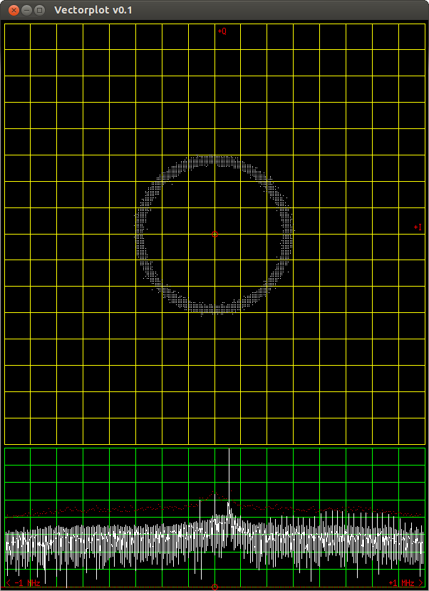
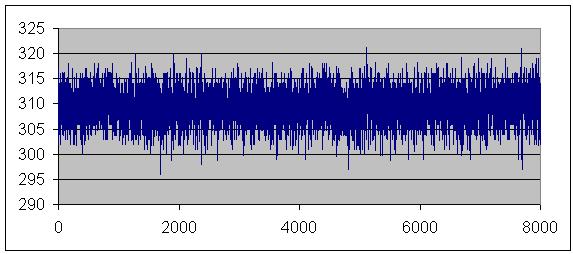
Right now it plots raw I and Q values on the plane as well as calculated FFT data. Since I haven't implemented clock recovery yet, signals appear as a circle (recall that for a frequency difference of N hz between the incoming signal and the sampling frequency, an N hz rotation around the IQ plane results - thus even a difference of a few hz is too quick to see anything but a circle). That shouldn't be very hard, and at that point it will become fully usable as a vector analyzer.
Code is here: https://github.com/jackcarrozzo/vectorplot.
Tuesday, October 22. 2013
Gyro-Stabilized DSLR Platform
I finally had time to put together one axis of my DSLR gyro frame today, and I am quite pleased with the results. The frame is big and heavy as it was originally intended to be a fixed-mount azimuth-altitude star and satellite rig for taking long exposures of planets and orbiting things, but it happened to be a good test bed for my gyro code. It's rock solid thus far:
Hopefully I will find time to build another axis soon so I can really see how solid both my math and my sensor are. I have a huge list of epic features to add to the project, too. I'm hoping I can get it solid enough to film with a 300mm lens and not need post-process stabilization.

Hopefully I will find time to build another axis soon so I can really see how solid both my math and my sensor are. I have a huge list of epic features to add to the project, too. I'm hoping I can get it solid enough to film with a 300mm lens and not need post-process stabilization.
Tuesday, June 4. 2013
FPGA QAM Generation
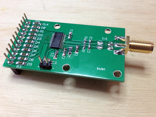
I recently drew up a board to connect a fast DAC to FPGA dev boards for the purpose of RF generation. I chose the DAC900E from TI as it's fast (165MS/s), pretty accurate (10-bit), and extremely easy to interface (latches values in on clock edges, doesn't require any setup or external stuff).
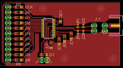
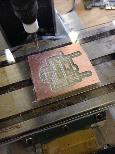
Normally I'd cut a simple one-layer board like this on my CNC mill, but I wanted to try a low cost hobbyist PCB fab I read about via Sparkfun. The did take a very long while, but came out beautifully. Also, when the boards finally arrived, I was pleased I had picked a DAC with so few external requirements to solder. The resistors are there to prevent an output buffer short in case I soldered badly, by the way - I don't own a hot air rework setup.

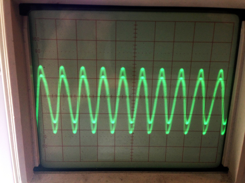
Right off the bat, I was pleased to see that my sine-generation test code worked great at various frequencies and bit depths (aliasing visible in the 2nd pic, its harmonics in the 3rd):
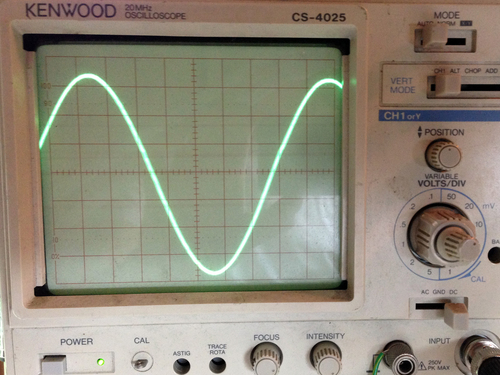


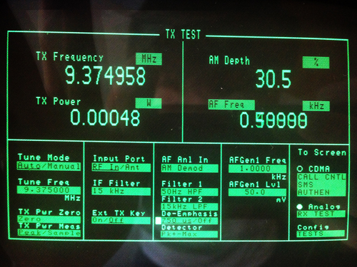
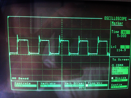
With a bit more hacking, I got the FT245R interface to work such that I send I and Q values via USB, the output value is calculated from an LUT (I originally was doing the math out, but hardware multiply is very slow), and sent to the DAC. In these pics, you can see that I was generating a 500-hz tone over an AM carrier at 9.375 MHz (the 3rd image is the AM-demodulated signal shown on the spectrum analyzer).
My code is on Github here. It's by no means robust or feature-rich, but it does work well in my opinion. When I have time, I'd like to see how far I can take this design. Assuming I don't find any unforseen roadblocks, the next step will be to make a board with two DAC900Es for I and Q generation that feed into a GHz-range QAM modulator that takes its carrier from a PLL on the FPGA, which will theoretically give me full TX control over a wide range of freqs.
Normally I'd cut a simple one-layer board like this on my CNC mill, but I wanted to try a low cost hobbyist PCB fab I read about via Sparkfun. The did take a very long while, but came out beautifully. Also, when the boards finally arrived, I was pleased I had picked a DAC with so few external requirements to solder. The resistors are there to prevent an output buffer short in case I soldered badly, by the way - I don't own a hot air rework setup.

Right off the bat, I was pleased to see that my sine-generation test code worked great at various frequencies and bit depths (aliasing visible in the 2nd pic, its harmonics in the 3rd):
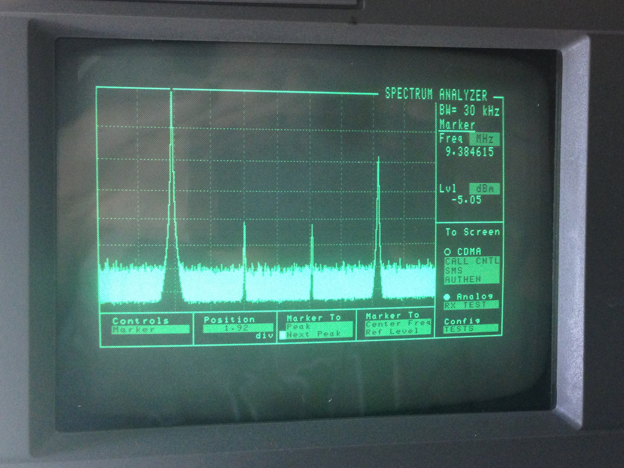
With a bit more hacking, I got the FT245R interface to work such that I send I and Q values via USB, the output value is calculated from an LUT (I originally was doing the math out, but hardware multiply is very slow), and sent to the DAC. In these pics, you can see that I was generating a 500-hz tone over an AM carrier at 9.375 MHz (the 3rd image is the AM-demodulated signal shown on the spectrum analyzer).


My code is on Github here. It's by no means robust or feature-rich, but it does work well in my opinion. When I have time, I'd like to see how far I can take this design. Assuming I don't find any unforseen roadblocks, the next step will be to make a board with two DAC900Es for I and Q generation that feed into a GHz-range QAM modulator that takes its carrier from a PLL on the FPGA, which will theoretically give me full TX control over a wide range of freqs.
Monday, March 25. 2013
Altera Quartus 12.1SP1 on Ubuntu 12.04 x86_64
Sunday, January 6. 2013
Dual DAC I+Q Generation and Carrier Modulation
I wanted a simple, easily-interfacable QAM source to test some code I had written for the RTL-SDR, so I put together two small boards: one with two SPI DACs to generate the I and Q inputs, and one board with a single analog QAM modulator on it that takes the carrier, I, and Q signals and outputs the modulated carrier.
First, I made the dual DAC board with two MAX515's - simple, 10-bit, SPI DACs.
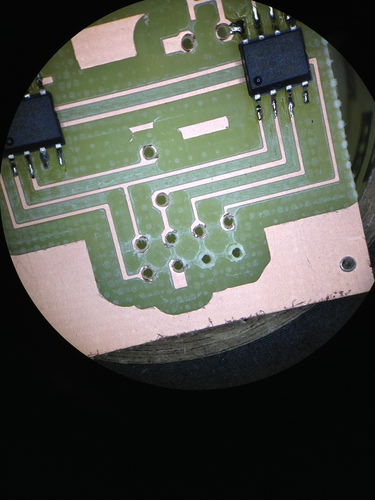
Aesthetically the board was not stunning - I used too large a drill for the through holes, and thus my pads were blown out. However, it was salavgable, so I continued putting it together and testing it by bit-banging the DACs with an FT245R dev board:
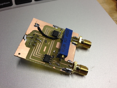
With that working well, I dead-bugged the modulator, a TRF370417 that will handle carrier freqs of 50 MHz through 6 GHz, to another board:

As pretty as that board turned out, it was unfortunately (and predictably) extremely noisy. Oh well, I suppose I will just have to make a proper board for all 3 chips...
First, I made the dual DAC board with two MAX515's - simple, 10-bit, SPI DACs.
Aesthetically the board was not stunning - I used too large a drill for the through holes, and thus my pads were blown out. However, it was salavgable, so I continued putting it together and testing it by bit-banging the DACs with an FT245R dev board:
With that working well, I dead-bugged the modulator, a TRF370417 that will handle carrier freqs of 50 MHz through 6 GHz, to another board:
As pretty as that board turned out, it was unfortunately (and predictably) extremely noisy. Oh well, I suppose I will just have to make a proper board for all 3 chips...
Wednesday, October 24. 2012
FSK Demod and Clock Recovery
Tuesday, August 26. 2008
On Handy Type of Virtualization
Friday, November 24. 2006
MIT Splash '06
Saturday, October 7. 2006
Neural Nets, Genetic Algorithms, and Cellular Automata
I read a book about biological computing recently, which got me interested in neural nets, genetic algorithms, and cellular automata. Perhaps I'll write up some science about each of them soon, but for now here are a few test codes I wrote to play with this stuff.
cells.c: A quick cellular automata simulation to play with different edge conditions and such. The linked version has my setup that allows a colony to continue living:
neural-backprop_g.c: Flat neural net model with back propagation. The important stuff is in main() if you want to play with it. I plan to write a proper library with this soon, so look for that.
Monday, February 13. 2006
DCIR Renderer
Many people can go on and on about the “beauty of math”: everything fits, and that’s amazing. Personally, I think math is pretty handy, but not always that pretty. But hey, I suppose I proved myself wrong in this latest project.
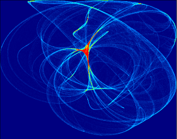
DCIR is a program that renders pretty pictures based on a chaotic set of functions- the DeJong equations:
You can get the source here: single machine (dcir.c), distributed (dcir_d.c)
While this method is great, it’s outrageously slow. Thus, the name suggests, DCIR is going to be “distributed”, or cluster-ready. At the moment the single-cpu code works great, but the MPI version leaves something to be desired… It sucks about 80 Mb/s of bandwidth, then dies. (Hey, it LOOKS like it should work )
I would like to thank the developers of Fyre. Fyre is basically a better version of what I’ve made. We discussed originally how they had things set up, particularly how their clustering worked. Their version included some nice editing tools that DCIR doesn’t, as well as a built in visualizer, and an animation option. The reason I wrote my own was more of a personal challenge than a real reason, though it will be nice to have a version that runs on MPI, as opposed to running the Fyre rendering server on all the nodes of the cluster.
For reference, here are some old images from the first version of DCIR, as well as some nice example I’ve made with Fyre (the antialiasing sure is nice):
Trial 1 at different exposures:
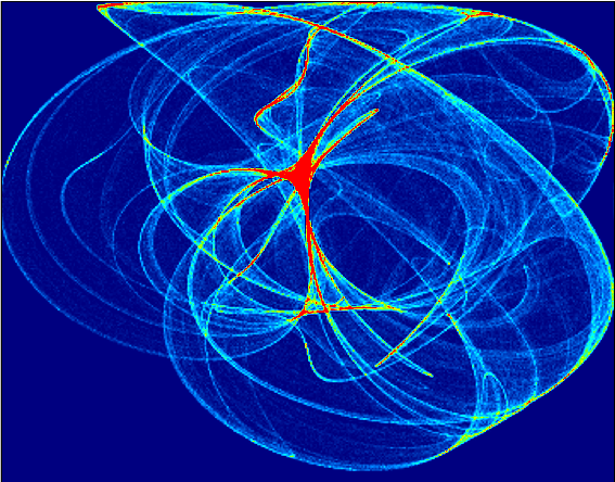
Trial 2:
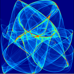

Fyre:


DCIR is a program that renders pretty pictures based on a chaotic set of functions- the DeJong equations:
x' = sin(ay) - cos(bx)Thus, starting with a random a,b,c,d,x, and y, we recursivly solve for an X’ and Y’ pair, then plug them back in while keeping a,b,c, and d constant. As opposed to your average function, such as f(x) = sin(x), these functions put out chaotic numbers. That is, they don’t follw any specific method, they simply hop around. But it turns out, they tend to hop into some areas more often than others. If you take a look at the images below, you’ll see what I mean. The brighter an area is, the more times an iteration “hopped” into that area. (Clicking on a picture will make it bigger, visualizations performed using Winfeild by Andrei Chernousov)
y' = sin(cx) - cos(dy)
You can get the source here: single machine (dcir.c), distributed (dcir_d.c)
While this method is great, it’s outrageously slow. Thus, the name suggests, DCIR is going to be “distributed”, or cluster-ready. At the moment the single-cpu code works great, but the MPI version leaves something to be desired… It sucks about 80 Mb/s of bandwidth, then dies. (Hey, it LOOKS like it should work )
I would like to thank the developers of Fyre. Fyre is basically a better version of what I’ve made. We discussed originally how they had things set up, particularly how their clustering worked. Their version included some nice editing tools that DCIR doesn’t, as well as a built in visualizer, and an animation option. The reason I wrote my own was more of a personal challenge than a real reason, though it will be nice to have a version that runs on MPI, as opposed to running the Fyre rendering server on all the nodes of the cluster.
For reference, here are some old images from the first version of DCIR, as well as some nice example I’ve made with Fyre (the antialiasing sure is nice):
Trial 1 at different exposures:
Trial 2:


Fyre:
Sunday, December 18. 2005
Low Altitude Temperature Profile
This project is to make a mathematical model of the temperature at low altitudes, and how it changes as the sun warms the earth. I’m basing the model around the one dimensional heat equation. Here's the output from the model with cold boundaries and a hot initial center, linearly distributed along the left wall (time is to the right):
The actual writing of the model was about as exciting as coding usually is… pretty boring to hear about. Thus, I’ll describe that process and how it works when I get a little more time, but at the moment here are the stories of testing the model using the rockets.
I started with 2 rockets, I currently have none. Thursday we went out and launched the first rocket without the computer in it to make sure it went where we wanted. It didn’t. In the past I’d used rockets with 4 motors and two stages, but separated, on either side of the body. As you can see here, this was not the case on the test rocket:
Here the bottom two motors were taped together… this turned out to be a bad idea. Apperently the motors do not burn at the same rate exactly, so when one finished and ignited its other stage, it was cast off… while still being attached to the other. Thus the bottom motor ripped off before it had lit its upper stage, leaving the rocket underpowered. Besides that, the launch rod we used in the test wasn’t nearly strong enoough, and the rocket ended up leaving the pad at about a 45-degree angle. This wasn’t so bad until the previously-explained stage switch, in which the sudden change in acceleration made the payload and thus the CG shift forward.This shifting mass caused the rocket to further rotate, and when the (single) upper stage motor fired, the rocket was pointed horizontally along the ground, about 200 feet up. The rocket continued missle-style for the last 3 seconds of the burn, then found its way into the trees at around 250 MPH. When we found it, there were peices strewn in a 25 ft radius of the actual payload.
The payload was intended to split from the body at the end of the burn. Unfourtunatly it got stuck, and the pressue inside the fusalage went instead out a different way: through the sides. So the payload came down with a section of fusalage, parachute still stuffed inside. As it went through the trees, the fins were stripped off. The wooden nose cone must have hit a tree, because I’ve never seen dents like that in such a large piece of wood…
This left us with 3 lessons to learn for the “real deal”: 1) Don’t strap the bottom stages together, 2) Make sure the payload detaches smoothly, 3) use a much stiffer launch rod. We did these things, and the first (and unfourtunatly final) launch went smoothly, though we had to knock it over about 30 degrees due to high wind. Thus the final altitude was around 2500 feet. As the rocket fell, the fusalage detached from the payload, and its wherabouts are currently unknown. However, the payload was succesfully recovered and read about 3/4 miles from the launch rod, near the intended landing spot:

Taking into account the issues the previous models had, I built a new rocket that was meant to be the final, perfect launch. This time rather than having such a wide and heavy body with a full BX24 motherboard in it, I soldered my own board, which included an FM transmitter for tracking. It was predicted to use half the engines (3 stages, no clusters) and go 120% as high.
As I was testing the board I built, I noticed an issue. The temperature sensor was probed every half-second, and the radio was pulsed every second. When the two happened to coincide (a reading while the radio was transmitting), the value read by the computer was very far off. I did not originally make this connection, and thought my board was simply bad. I hooked a probe up to the positive of my battery, and poked the pin that was reading the temperature sensor. This should have returned a full HIGH value, or a 1024. Instead, the chip crashed, and never came back.
Woops… I had forgotten that the battery (9v) was going into a 5v regulator before the computer. Thus, the highest voltage expected by the chip was 5v. All the manuals with the chip indicate that reverse polarity will instantly kill a chip. When I applied the 9v, the comparator tested it against 5v, allowed current to flow backwards, and beasted the poor device.
It was 3am on launch day, and I didn’t have another chip. I decided that I might as well launch the rocket, because rockets are cool. I was rewarded with the most awesome landing yet:
Epic!
The actual writing of the model was about as exciting as coding usually is… pretty boring to hear about. Thus, I’ll describe that process and how it works when I get a little more time, but at the moment here are the stories of testing the model using the rockets.
I started with 2 rockets, I currently have none. Thursday we went out and launched the first rocket without the computer in it to make sure it went where we wanted. It didn’t. In the past I’d used rockets with 4 motors and two stages, but separated, on either side of the body. As you can see here, this was not the case on the test rocket:
Here the bottom two motors were taped together… this turned out to be a bad idea. Apperently the motors do not burn at the same rate exactly, so when one finished and ignited its other stage, it was cast off… while still being attached to the other. Thus the bottom motor ripped off before it had lit its upper stage, leaving the rocket underpowered. Besides that, the launch rod we used in the test wasn’t nearly strong enoough, and the rocket ended up leaving the pad at about a 45-degree angle. This wasn’t so bad until the previously-explained stage switch, in which the sudden change in acceleration made the payload and thus the CG shift forward.This shifting mass caused the rocket to further rotate, and when the (single) upper stage motor fired, the rocket was pointed horizontally along the ground, about 200 feet up. The rocket continued missle-style for the last 3 seconds of the burn, then found its way into the trees at around 250 MPH. When we found it, there were peices strewn in a 25 ft radius of the actual payload.
The payload was intended to split from the body at the end of the burn. Unfourtunatly it got stuck, and the pressue inside the fusalage went instead out a different way: through the sides. So the payload came down with a section of fusalage, parachute still stuffed inside. As it went through the trees, the fins were stripped off. The wooden nose cone must have hit a tree, because I’ve never seen dents like that in such a large piece of wood…
This left us with 3 lessons to learn for the “real deal”: 1) Don’t strap the bottom stages together, 2) Make sure the payload detaches smoothly, 3) use a much stiffer launch rod. We did these things, and the first (and unfourtunatly final) launch went smoothly, though we had to knock it over about 30 degrees due to high wind. Thus the final altitude was around 2500 feet. As the rocket fell, the fusalage detached from the payload, and its wherabouts are currently unknown. However, the payload was succesfully recovered and read about 3/4 miles from the launch rod, near the intended landing spot:
Taking into account the issues the previous models had, I built a new rocket that was meant to be the final, perfect launch. This time rather than having such a wide and heavy body with a full BX24 motherboard in it, I soldered my own board, which included an FM transmitter for tracking. It was predicted to use half the engines (3 stages, no clusters) and go 120% as high.
As I was testing the board I built, I noticed an issue. The temperature sensor was probed every half-second, and the radio was pulsed every second. When the two happened to coincide (a reading while the radio was transmitting), the value read by the computer was very far off. I did not originally make this connection, and thought my board was simply bad. I hooked a probe up to the positive of my battery, and poked the pin that was reading the temperature sensor. This should have returned a full HIGH value, or a 1024. Instead, the chip crashed, and never came back.
Woops… I had forgotten that the battery (9v) was going into a 5v regulator before the computer. Thus, the highest voltage expected by the chip was 5v. All the manuals with the chip indicate that reverse polarity will instantly kill a chip. When I applied the 9v, the comparator tested it against 5v, allowed current to flow backwards, and beasted the poor device.
It was 3am on launch day, and I didn’t have another chip. I decided that I might as well launch the rocket, because rockets are cool. I was rewarded with the most awesome landing yet:
Epic!
Sunday, November 27. 2005
Genetic Algorithms
Wednesday, November 9. 2005
MIT Splash, Nov. 19-20. Come!
Saturday, October 29. 2005
nBody Simulations
I did a project in CS at school to simulate the movement of free bodies with gravity.

At each timestep, each body's force is evaluated with respect to every other body, vector summed, then applied. No sense writing out all the gory details here since I wrote this in a paper for class!
Here's the source, and a video clip of the simulation.
Note from 2012: don't judge my physics or writing by that PDF! Leaving it for posterity, but I've learned a bit since then...
Email me:
jack {@} crepinc.com
Recent Projects:
Analog HF Transmitter
Audi ECU Reverse Engineering
Dual DAC QAM Modulator
FPGA QAM Modulator
Geiger Counter
Gyro-Stabilized DSLR Platform
Hybrid Rocket Engines
Turbocharger Controller
WWVB Rx and Tx
Older Projects:
Balancing Bot
Capacitor Array
CNC Mill
DCIR Renderer
Electric Gokart
Hovercraft
Low Alt. Temp. Model
Shopping Cart Locker
Trebuchet
My Twitter occasionally shows projects I'm working on.
My GitHub has code from a few projects on it.