Update: Now that I actually know how to machine things, I’m going to revamp the Kart next time I’m home. Real bearings for the steering assembly, pedals and a floorboard, etc. Should be interesting…
I built this “Kart” basically because I wanted to see if I was good at building large (or larger than normal) things, and to satisfy a “project” requirment for my physics class. While most people built small electronics projects on breadboards, I built this. People were pretty surprised.
Update to the update: The frame got turned into a trike for the hang glider, and the motor got imported to a scooter. Both were epic.
Frame
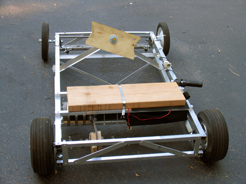
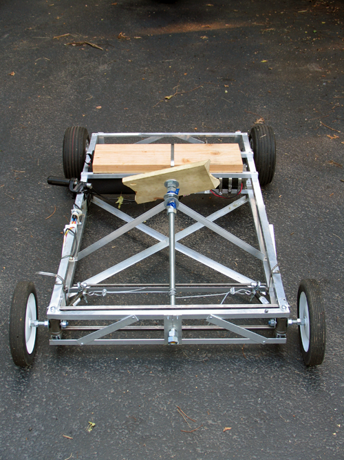
The frame was designed (in my head, since I can’t draw) to be very light, but hopefully still fairly strong. Four 1″ square aluminum stock bars run the length of the frame as 4 edges of a box. Each side of this “box” is then held the proper distance apart by perpendicular flat stock and held rigid by 2 opposite-direction diagnals of either flat stock or square stock.
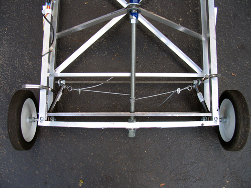
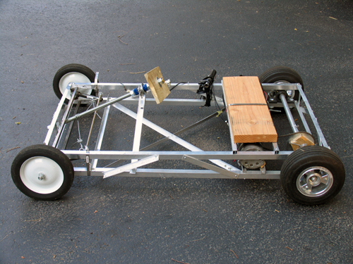
The cross peices that go between the frame sides in the front are 1/2″ inch steel square stock. It is absolutly key that these side sections stay the same distance apart, as they control the cambre of the wheels. The steel is held in place by threaded rod. (I would have used aluminum, but Home Depot is terrible at restocking and never had enough.)
The front wheels are lame garden wheels from Home Depot (about $8 each) with built in bearings. It remains to be seen how long the bearings will last, but they haven’t fallen out yet…
Steering
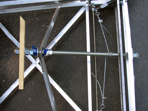
The steering idea was conceived by Sean Manix and Joe Gage in a gravity-powered car we built long ago. I modified the design somewhat to work here. Basically, the system works as a rack and pinion system does, minus the rack and the pinion. The tierod keeps outward tension on the steering arms so that they stay the proper distance apart and the wheels stay parallel; the wire pulls the whole sytem to one side or the other to steer while at the same time keeping tension on the steering arms so they stay on the tierod.
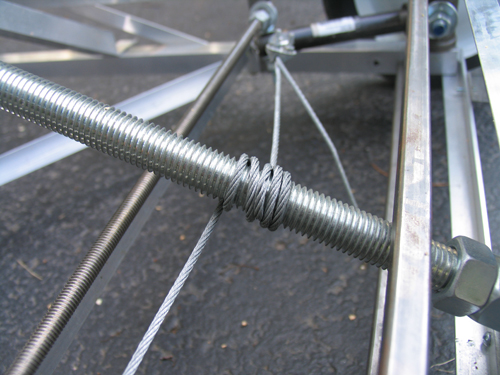
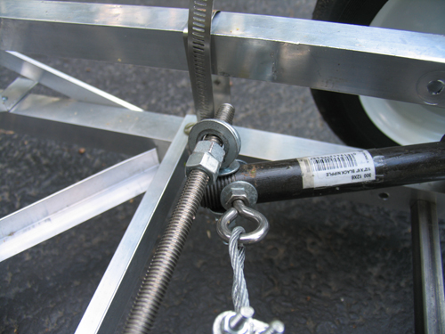
Yes, the steering arms are made of plumbing equipment.
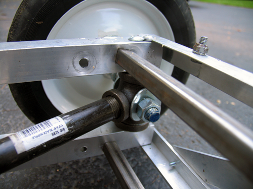
Inside those plumbing T’s, bolts come in from both square sections of frame. Roller skate bearings (that I had around and just happened to fit) go over the bolts and space the plumbing to sit in the center. I then put the T’s on the drill press and put the 1/2″ holes in them. Let me tell you, that was scary. The bit has a tendancy to catch coming out the other side, so the whole T arm unit spins around the bit fast enough to break your arm.
As inaccurate as this looks, it actual is very smooth and tight. The steering feels nice while youre driving.
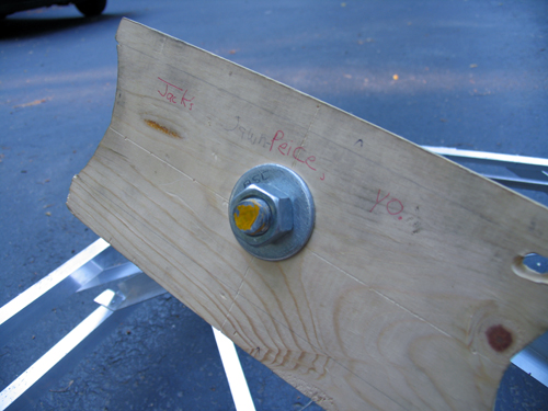
…don’t ask, it’s a school thing somebody wrote. But yes, that is the “steering plank”.
Drive Train
The motor is from an electric scooter. It’s 750 Watts… in pure energy, 1 horsepower = 746 Watts, but I think here the 750w describe amount of power the motor pulls from the batteries, not the mechanical energy put out. Since the motor is likely only moderatly efficient, I’d say it’s in the half-horsepower range.

My girlfriend Erica is building a kart on the same design as this one. I helped her get her motor… hers is 1200w. I think I’ll still be able to beat her once I figure out how to put some sort of transmission on this thing. The chain and rear cog are from the scooter too.
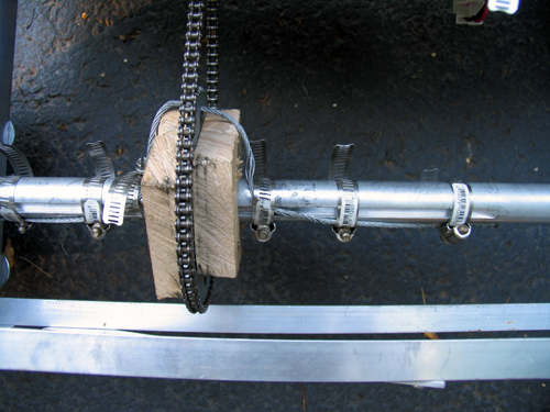
The bain of my existance… the blocks holding the rear sproket are badly made and thus wobble. The axle (1″) has a keyway in it, and the sproken has a 2″ hole. Logically, we’d make spacers to simply hold it in the center, and the spacers would fit the keyway to spin it. I built two of these out of hard wood. I cut the 1″ and keyway with a coping saw (which was a hard process), screwed the whole thing together, and slapped the chain on. It looked perfect. As soon as I touched the throttle, the keyways sheared off (wood doesn’t deal with shear stress very well) and the whole unit simply spun.
Despite efforts to make some sort of key, each time something would slip or shear off as I don't have access to any sort of metal shop. Thus, the steal cable goes through the hole in the sproket and get band clamped to the axle. The wood simply acts to keep the sproket in the right place, and the cable deals with transfering the torque to the axle. It’s ugly, and the chain pops off occasionally. I need to make some sort of mount from aluminum…
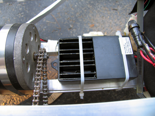
This is basically just a large version of the electronic speed controller in a remote control car. Rather than having huge variable resistors, the “ESC” as its called simply pulses the motor very quickly, and by varying how many of these pulses are “on” and “off” we vary the speed.
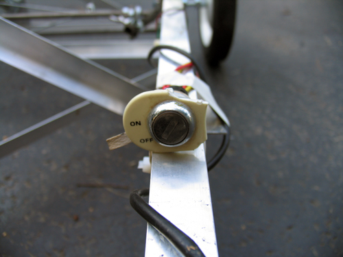
Ignition… because I can.
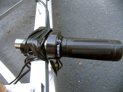
The throttle from the scooter. Yes, it is taped to the side. I haven’t had a chance to fasion some sort of pedal yet.
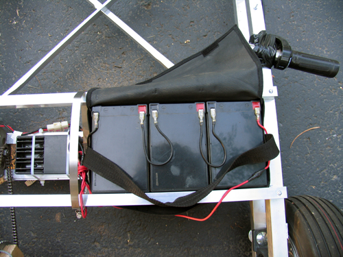
Three 7 Ah lead acid batteries power this 36v beast… they’re heavy.
Final Thoughts
In case you were wondering, there are no brakes. I haven’t gotten to that yet. But hey, when I get to the transmission and the throttle pedal, perhaps a brake might appear.


