Tuesday, October 22. 2013
Gyro-Stabilized DSLR Platform
I finally had time to put together one axis of my DSLR gyro frame today, and I am quite pleased with the results. The frame is big and heavy as it was originally intended to be a fixed-mount azimuth-altitude star and satellite rig for taking long exposures of planets and orbiting things, but it happened to be a good test bed for my gyro code. It's rock solid thus far:
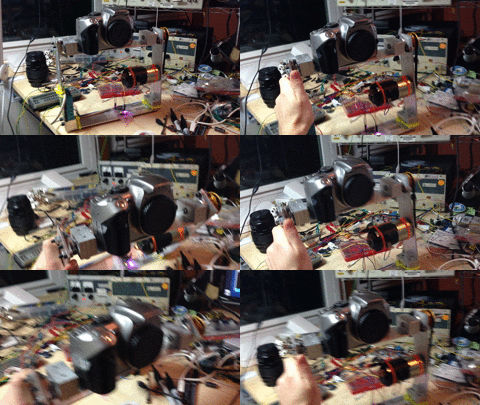
Hopefully I will find time to build another axis soon so I can really see how solid both my math and my sensor are. I have a huge list of epic features to add to the project, too. I'm hoping I can get it solid enough to film with a 300mm lens and not need post-process stabilization.

Hopefully I will find time to build another axis soon so I can really see how solid both my math and my sensor are. I have a huge list of epic features to add to the project, too. I'm hoping I can get it solid enough to film with a 300mm lens and not need post-process stabilization.
Wednesday, November 21. 2012
Turbo Controller
My car, an Audi A4 1.8t, opens the wastegate at 8psi above atmospheric pressure, stock. Since clearly more power is better (and building stuff is entertaining), I needed to make something to adjust the boost setting.
In standard turbocharger systems, there is simply a diaphragm that pops at the set pressure, and allows air to flow into the wastegate, reducing the amount of flow through the turbine, thus lowering the output pressure of the compressor. In the audi, there is a valve called the N75 with a two-conductor cable and 3 hoses connected to it: the turbo compressor tap, the wastegate input, and the airbox (for clean air feed under vacuum). I assumed this was simply a solenoid valve, and energizing it causes it to open. As such, my first code revision simply emulated a manual boost controller: at the set pressure (controlled by potentiometer), energize the valve and open the wastegate.

I hacked this all into the car in an evening with an arduino and an N-channel MOSFET (I KNEW that cat5 I ran into the engine compartment would come in handy...) and went for a spin. The results were... unexpected. The car drove just like it did normally and my manifold pressure gauge didn't register anything abnormal, except for one blip where the car unexpectedly made insane power while I was turning a corner. Hmmm.
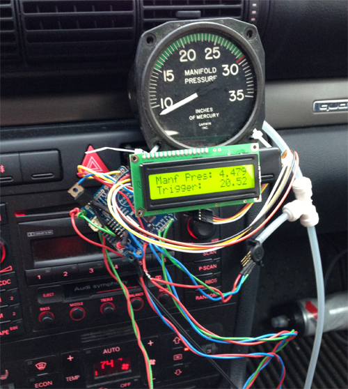
I plugged the N75 back into the ECU and put my scope on it. Ah! It was being PWM'd!
It turns out the the N75 is actually a spring-controlled valve that begins releasing air at it's set pressure of 8psi over ambient. However, the solenoid coil in it can be pushed in either direction to lower or raise the setpoint. So, my logic was backwards: in order to make more boost, you energize the coil to push against the spring. I adjusted my code to PWM the coil, pushing hardest just above 8psi boost then tapering off to the setpoint for a smooth transition. It works great! The car makes significantly more power running 20psi of boost.
The only issue with that setup was the placement of my pressure transducer: I connected it to the tap from the intake manifold, post-throttle. This means that the turbo can be ramming out 30psi, but if the throttle is closed we still see vacuum. This wouldn't be a huge issue, except that the ECU's manifold pressure sensor is located pre-throttle, and it (a) sets the mixture and (b) cuts the injectors if it sees a dangerous level of boost (about 22psi). Whenever I would sharply accelerate or take my foot off the gas, the resulting spike from the throttle movement would send the pre-throttle pressure over that limit and cause the injectors to cut then surge back - not very great.
I have the system out of the car at the moment to install up front with the new pressure transducer placement just after the turbo. Should be splendid.
In standard turbocharger systems, there is simply a diaphragm that pops at the set pressure, and allows air to flow into the wastegate, reducing the amount of flow through the turbine, thus lowering the output pressure of the compressor. In the audi, there is a valve called the N75 with a two-conductor cable and 3 hoses connected to it: the turbo compressor tap, the wastegate input, and the airbox (for clean air feed under vacuum). I assumed this was simply a solenoid valve, and energizing it causes it to open. As such, my first code revision simply emulated a manual boost controller: at the set pressure (controlled by potentiometer), energize the valve and open the wastegate.

I hacked this all into the car in an evening with an arduino and an N-channel MOSFET (I KNEW that cat5 I ran into the engine compartment would come in handy...) and went for a spin. The results were... unexpected. The car drove just like it did normally and my manifold pressure gauge didn't register anything abnormal, except for one blip where the car unexpectedly made insane power while I was turning a corner. Hmmm.

I plugged the N75 back into the ECU and put my scope on it. Ah! It was being PWM'd!
It turns out the the N75 is actually a spring-controlled valve that begins releasing air at it's set pressure of 8psi over ambient. However, the solenoid coil in it can be pushed in either direction to lower or raise the setpoint. So, my logic was backwards: in order to make more boost, you energize the coil to push against the spring. I adjusted my code to PWM the coil, pushing hardest just above 8psi boost then tapering off to the setpoint for a smooth transition. It works great! The car makes significantly more power running 20psi of boost.
The only issue with that setup was the placement of my pressure transducer: I connected it to the tap from the intake manifold, post-throttle. This means that the turbo can be ramming out 30psi, but if the throttle is closed we still see vacuum. This wouldn't be a huge issue, except that the ECU's manifold pressure sensor is located pre-throttle, and it (a) sets the mixture and (b) cuts the injectors if it sees a dangerous level of boost (about 22psi). Whenever I would sharply accelerate or take my foot off the gas, the resulting spike from the throttle movement would send the pre-throttle pressure over that limit and cause the injectors to cut then surge back - not very great.
I have the system out of the car at the moment to install up front with the new pressure transducer placement just after the turbo. Should be splendid.
Saturday, May 5. 2012
Hybrid Rockets: v2
Inspired by the wild success of the previous rocket engines, I machined some cases and nozzles from aluminium to see what would happen. What happened was exactly what was expected: epic thrust, followed shortly by epic structural failure.
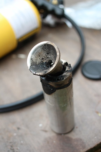
I machined this beautiful nozzle on the lathe and was extremly proud of it. I knew that, being aluminium, it wouldn't last more than a few seconds assuming ignition was acheived, but it sure was awesome until that point.
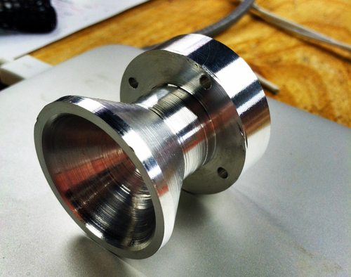
And lo, it failed just like expected (through the thin parts), but not before making an absolutely epic flame plume and a noise I can't quite describe other than LOUD. But check out that ablation!
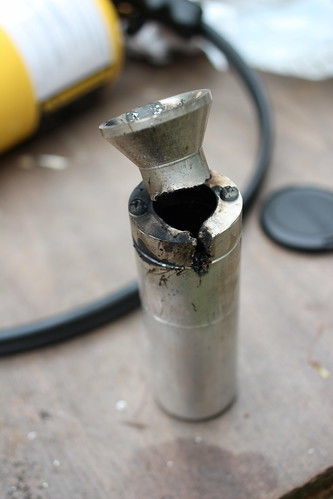
Since we still had fuels but no more nozzles nor cases, we decided we better burn through a few more home depot plumbing engines. We succeeded wildly at this goal as well.
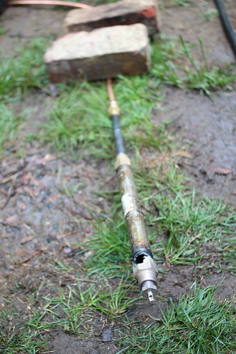

After that was through, we realized we had the new o2 regulator that might make the 10' black iron 'engines' work a bit better. With much haste, the motor was connected and ignited.


Unfortunately I didn't get any pictures of the actual firing as I was hiding behind the most dense objects I could find, in this case the o2 tanks. Suffice to say the cloud of deathgas was too thick to see through and expansive enough to cover an airport. Great success! We still only got about 1' of the PVC burning, we're going to step up to either multiple o2 injectors, or liquid o2.
I machined this beautiful nozzle on the lathe and was extremly proud of it. I knew that, being aluminium, it wouldn't last more than a few seconds assuming ignition was acheived, but it sure was awesome until that point.

And lo, it failed just like expected (through the thin parts), but not before making an absolutely epic flame plume and a noise I can't quite describe other than LOUD. But check out that ablation!


Since we still had fuels but no more nozzles nor cases, we decided we better burn through a few more home depot plumbing engines. We succeeded wildly at this goal as well.


After that was through, we realized we had the new o2 regulator that might make the 10' black iron 'engines' work a bit better. With much haste, the motor was connected and ignited.


Unfortunately I didn't get any pictures of the actual firing as I was hiding behind the most dense objects I could find, in this case the o2 tanks. Suffice to say the cloud of deathgas was too thick to see through and expansive enough to cover an airport. Great success! We still only got about 1' of the PVC burning, we're going to step up to either multiple o2 injectors, or liquid o2.
Friday, April 27. 2012
Hybrid Rockets: v1
If you've followed my blog for a while (years) you'll note I like rockets. In the more recent years there had been a significant lack of proper exothermic reactions, and this needed to change.
I started matlabbing and thinking of good ways to do liquid-propellant motors, but thought that perhaps I should attempt the more-simple hybrid rocket engines first. On a Saturday morning I hit Home Depot and purchased all the things one needs to make a simple hybrid motor: oxygen, a rubber hose or plastic stock, and enough pipe fittings to put a small hole on the end.
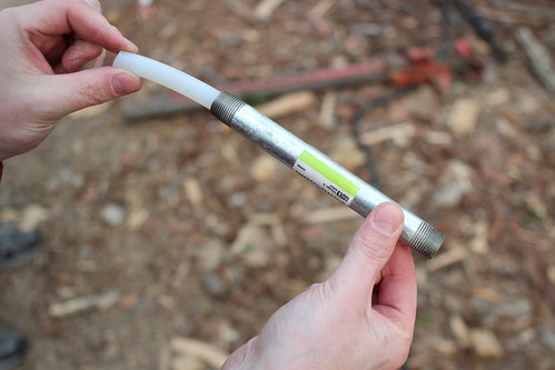
Here you can see I have some rubber hose (the fuel) inside a metal pipe. When the oxygen passes through the hose, the pair REALLY want to burn. Below, the whole setup assembled:
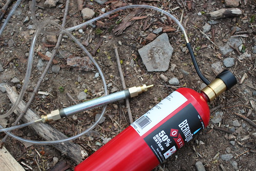
The home depot ox tank comes with a tiny regulator, which later became a problem. However the setup on a whole is extremely simple. Ignition was achieved by inserting a bit of rubber through the nozzle and touching the tube inside, flowing a small amount of ox through the system, and lighting the rubber with a torch. Worked first time!
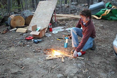
As stated, we soon needed more oxygen. Luckily Ken had his welding setup on hand....

As you can see from Ken's face, much more mass flow happened...
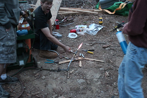
Of course, things quickly progressed from there. Ken noted he had an idea, and quickly returned with a 10' length of black iron pipe and a similar piece of PVC that fit inside. He drilled holes in two caps, threaded them on, and we were ready to roll.

Fortunately enough for us, we could only get enough oxygen flow for about 6" of PVC to burn. Regardless, that produced a TON of black deathsmoke, heat, and noise. Had we had a larger flow regulator, the thing would have killed everyone in town. We'll have to order one for next time.
I started matlabbing and thinking of good ways to do liquid-propellant motors, but thought that perhaps I should attempt the more-simple hybrid rocket engines first. On a Saturday morning I hit Home Depot and purchased all the things one needs to make a simple hybrid motor: oxygen, a rubber hose or plastic stock, and enough pipe fittings to put a small hole on the end.

Here you can see I have some rubber hose (the fuel) inside a metal pipe. When the oxygen passes through the hose, the pair REALLY want to burn. Below, the whole setup assembled:

The home depot ox tank comes with a tiny regulator, which later became a problem. However the setup on a whole is extremely simple. Ignition was achieved by inserting a bit of rubber through the nozzle and touching the tube inside, flowing a small amount of ox through the system, and lighting the rubber with a torch. Worked first time!

As stated, we soon needed more oxygen. Luckily Ken had his welding setup on hand....

As you can see from Ken's face, much more mass flow happened...

Of course, things quickly progressed from there. Ken noted he had an idea, and quickly returned with a 10' length of black iron pipe and a similar piece of PVC that fit inside. He drilled holes in two caps, threaded them on, and we were ready to roll.

Fortunately enough for us, we could only get enough oxygen flow for about 6" of PVC to burn. Regardless, that produced a TON of black deathsmoke, heat, and noise. Had we had a larger flow regulator, the thing would have killed everyone in town. We'll have to order one for next time.
Thursday, September 29. 2011
Sonerai IIL Running Happily
Finally got the motor back on the plane after tearing it down and putting it back together. It's much happier now...
Vimeo link: here.
Vimeo link: here.
Monday, February 15. 2010
Jet Powered Hovercraft
Chris and I decided we needed to build a propane powered jet engine using a turbo from a car. Given my previous successes with hovercrafts, of course we needed to step the game up.
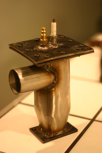
Our combustion chamber takes air from the compressor, swirls it around with liquid propane, then burns it, creating a huge expansion of the inputs. The gases then pass out into the turbine section of the turbo, spinning the compressor faster, and so on. The brass nozzle you see is the propane connection. The sparkplug is to start the combustion, but the flame is self-sustaining once it's running.
We rigged the combustion chamber to the output of the shop vac, connected the spark coils, and let a little gas flow. Much to our surprise, a significant roar was produced! We were even more pleased when the roar continued after we switched off the sparkplug. Below, Eric inspects the turbo.
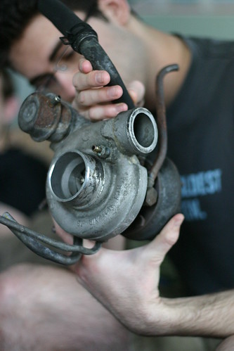
When we put it all together, the unit was spinning at upwards of 120 krpm, and blasting the rhododendrons around across the yard. We also used it for snow clearing.
While we still had it running (ie before it was scavenged for parts), two exciting things happened. Once, when we drilled out the propane fittings to get more gas through. This made the engine run at a higher compression of course. Right as Ken reached across the motor to poke a gauge, the cold air manifold from the compressor separated from the combustion chamber, and the resulting gas instantly melted all the hair off Ken's arm. However perhaps more amusing was the time the bearing's oil seal failed during a full-thrust run. 60psi hot, thin motor oil sprayed into the turbine housing and instantly turned to smoke. The sheer amount of black death coming out the back of that jet engine is an image I won't soon forget. epic.

Our combustion chamber takes air from the compressor, swirls it around with liquid propane, then burns it, creating a huge expansion of the inputs. The gases then pass out into the turbine section of the turbo, spinning the compressor faster, and so on. The brass nozzle you see is the propane connection. The sparkplug is to start the combustion, but the flame is self-sustaining once it's running.

We rigged the combustion chamber to the output of the shop vac, connected the spark coils, and let a little gas flow. Much to our surprise, a significant roar was produced! We were even more pleased when the roar continued after we switched off the sparkplug. Below, Eric inspects the turbo.

When we put it all together, the unit was spinning at upwards of 120 krpm, and blasting the rhododendrons around across the yard. We also used it for snow clearing.
While we still had it running (ie before it was scavenged for parts), two exciting things happened. Once, when we drilled out the propane fittings to get more gas through. This made the engine run at a higher compression of course. Right as Ken reached across the motor to poke a gauge, the cold air manifold from the compressor separated from the combustion chamber, and the resulting gas instantly melted all the hair off Ken's arm. However perhaps more amusing was the time the bearing's oil seal failed during a full-thrust run. 60psi hot, thin motor oil sprayed into the turbine housing and instantly turned to smoke. The sheer amount of black death coming out the back of that jet engine is an image I won't soon forget. epic.
Thursday, April 27. 2006
Electric Gokart
Update: Now that I actually know how to machine things, I’m going to revamp the Kart next time I’m home. Real bearings for the steering assembly, pedals and a floorboard, etc. Should be interesting…
I built this “Kart” basically because I wanted to see if I was good at building large (or larger than normal) things, and to satisfy a “project” requirment for my physics class. While most people built small electronics projects on breadboards, I built this. People were pretty surprised.
Update to the update: The frame got turned into a trike for the hang glider, and the motor got imported to a scooter. Both were epic.
Frame
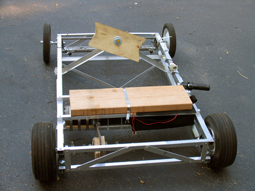
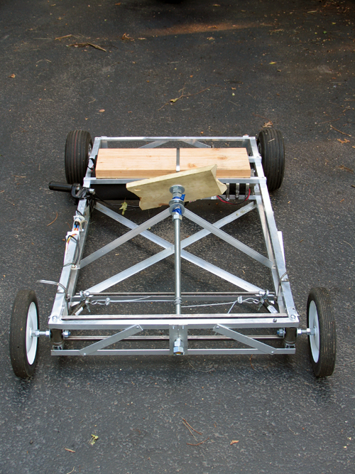
The frame was designed (in my head, since I can’t draw) to be very light, but hopefully still fairly strong. Four 1″ square aluminum stock bars run the length of the frame as 4 edges of a box. Each side of this “box” is then held the proper distance apart by perpendicular flat stock and held rigid by 2 opposite-direction diagnals of either flat stock or square stock.
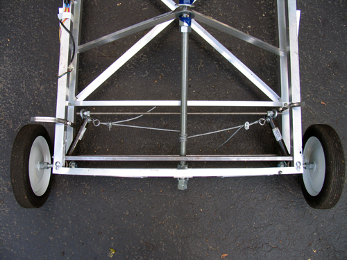
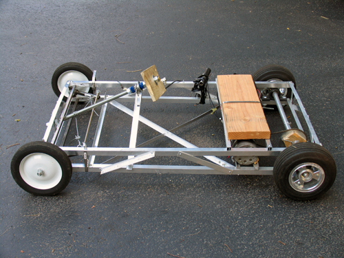
The cross peices that go between the frame sides in the front are 1/2″ inch steel square stock. It is absolutly key that these side sections stay the same distance apart, as they control the cambre of the wheels. The steel is held in place by threaded rod. (I would have used aluminum, but Home Depot is terrible at restocking and never had enough.)
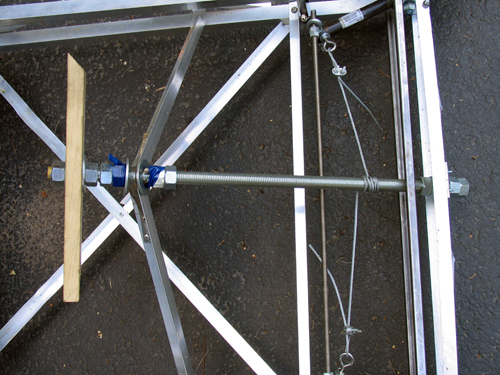
The front wheels are lame garden wheels from Home Depot (about $8 each) with built in bearings. It remains to be seen how long the bearings will last, but they haven’t fallen out yet…
Steering
The steering idea was conceived by Sean Manix and Joe Gage in a gravity-powered car we built long ago. I modified the design somewhat to work here. Basically, the system works as a rack and pinion system does, minus the rack and the pinion. The tierod keeps outward tension on the steering arms so that they stay the proper distance apart and the wheels stay parallel; the wire pulls the whole sytem to one side or the other to steer while at the same time keeping tension on the steering arms so they stay on the tierod.
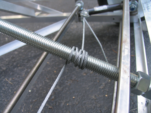
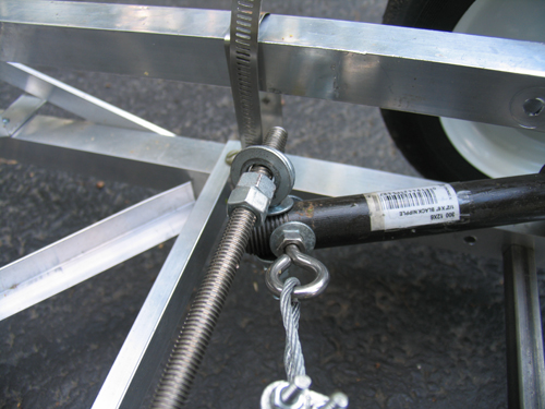
Yes, the steering arms are made of plumbing equipment.
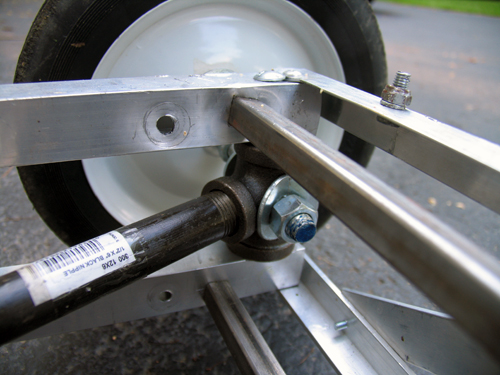
Inside those plumbing T’s, bolts come in from both square sections of frame. Roller skate bearings (that I had around and just happened to fit) go over the bolts and space the plumbing to sit in the center. I then put the T’s on the drill press and put the 1/2″ holes in them. Let me tell you, that was scary. The bit has a tendancy to catch coming out the other side, so the whole T arm unit spins around the bit fast enough to break your arm.
As inaccurate as this looks, it actual is very smooth and tight. The steering feels nice while youre driving.
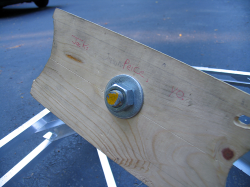
…don’t ask, it’s a school thing somebody wrote. But yes, that is the “steering plank”.
Drive Train
The motor is from an electric scooter. It’s 750 Watts… in pure energy, 1 horsepower = 746 Watts, but I think here the 750w describe amount of power the motor pulls from the batteries, not the mechanical energy put out. Since the motor is likely only moderatly efficient, I’d say it’s in the half-horsepower range.

My girlfriend Erica is building a kart on the same design as this one. I helped her get her motor… hers is 1200w. I think I’ll still be able to beat her once I figure out how to put some sort of transmission on this thing. The chain and rear cog are from the scooter too.
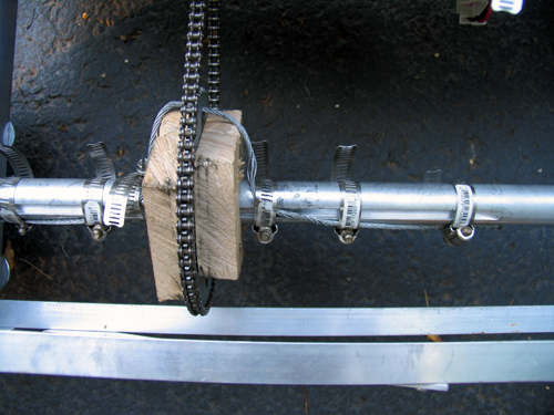
The bain of my existance… the blocks holding the rear sproket are badly made and thus wobble. The axle (1″) has a keyway in it, and the sproken has a 2″ hole. Logically, we’d make spacers to simply hold it in the center, and the spacers would fit the keyway to spin it. I built two of these out of hard wood. I cut the 1″ and keyway with a coping saw (which was a hard process), screwed the whole thing together, and slapped the chain on. It looked perfect. As soon as I touched the throttle, the keyways sheared off (wood doesn’t deal with shear stress very well) and the whole unit simply spun.
Despite efforts to make some sort of key, each time something would slip or shear off as I don't have access to any sort of metal shop. Thus, the steal cable goes through the hole in the sproket and get band clamped to the axle. The wood simply acts to keep the sproket in the right place, and the cable deals with transfering the torque to the axle. It’s ugly, and the chain pops off occasionally. I need to make some sort of mount from aluminum…
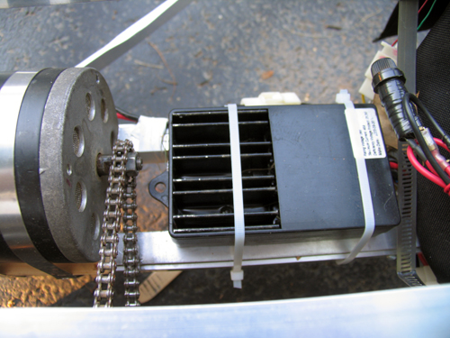
This is basically just a large version of the electronic speed controller in a remote control car. Rather than having huge variable resistors, the “ESC” as its called simply pulses the motor very quickly, and by varying how many of these pulses are “on” and “off” we vary the speed.
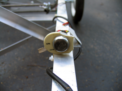
Ignition… because I can.
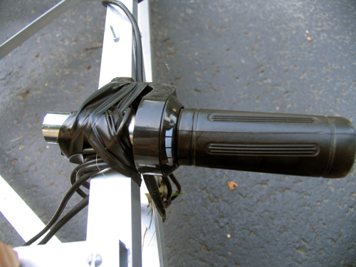
The throttle from the scooter. Yes, it is taped to the side. I haven’t had a chance to fasion some sort of pedal yet.
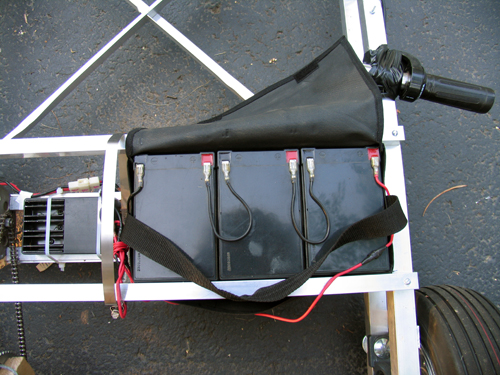
Three 7 Ah lead acid batteries power this 36v beast… they’re heavy.
Final Thoughts
In case you were wondering, there are no brakes. I haven’t gotten to that yet. But hey, when I get to the transmission and the throttle pedal, perhaps a brake might appear.
I built this “Kart” basically because I wanted to see if I was good at building large (or larger than normal) things, and to satisfy a “project” requirment for my physics class. While most people built small electronics projects on breadboards, I built this. People were pretty surprised.
Update to the update: The frame got turned into a trike for the hang glider, and the motor got imported to a scooter. Both were epic.
Frame


The frame was designed (in my head, since I can’t draw) to be very light, but hopefully still fairly strong. Four 1″ square aluminum stock bars run the length of the frame as 4 edges of a box. Each side of this “box” is then held the proper distance apart by perpendicular flat stock and held rigid by 2 opposite-direction diagnals of either flat stock or square stock.


The cross peices that go between the frame sides in the front are 1/2″ inch steel square stock. It is absolutly key that these side sections stay the same distance apart, as they control the cambre of the wheels. The steel is held in place by threaded rod. (I would have used aluminum, but Home Depot is terrible at restocking and never had enough.)

The front wheels are lame garden wheels from Home Depot (about $8 each) with built in bearings. It remains to be seen how long the bearings will last, but they haven’t fallen out yet…
Steering
The steering idea was conceived by Sean Manix and Joe Gage in a gravity-powered car we built long ago. I modified the design somewhat to work here. Basically, the system works as a rack and pinion system does, minus the rack and the pinion. The tierod keeps outward tension on the steering arms so that they stay the proper distance apart and the wheels stay parallel; the wire pulls the whole sytem to one side or the other to steer while at the same time keeping tension on the steering arms so they stay on the tierod.


Yes, the steering arms are made of plumbing equipment.

Inside those plumbing T’s, bolts come in from both square sections of frame. Roller skate bearings (that I had around and just happened to fit) go over the bolts and space the plumbing to sit in the center. I then put the T’s on the drill press and put the 1/2″ holes in them. Let me tell you, that was scary. The bit has a tendancy to catch coming out the other side, so the whole T arm unit spins around the bit fast enough to break your arm.
As inaccurate as this looks, it actual is very smooth and tight. The steering feels nice while youre driving.

…don’t ask, it’s a school thing somebody wrote. But yes, that is the “steering plank”.
Drive Train
The motor is from an electric scooter. It’s 750 Watts… in pure energy, 1 horsepower = 746 Watts, but I think here the 750w describe amount of power the motor pulls from the batteries, not the mechanical energy put out. Since the motor is likely only moderatly efficient, I’d say it’s in the half-horsepower range.

My girlfriend Erica is building a kart on the same design as this one. I helped her get her motor… hers is 1200w. I think I’ll still be able to beat her once I figure out how to put some sort of transmission on this thing. The chain and rear cog are from the scooter too.

The bain of my existance… the blocks holding the rear sproket are badly made and thus wobble. The axle (1″) has a keyway in it, and the sproken has a 2″ hole. Logically, we’d make spacers to simply hold it in the center, and the spacers would fit the keyway to spin it. I built two of these out of hard wood. I cut the 1″ and keyway with a coping saw (which was a hard process), screwed the whole thing together, and slapped the chain on. It looked perfect. As soon as I touched the throttle, the keyways sheared off (wood doesn’t deal with shear stress very well) and the whole unit simply spun.
Despite efforts to make some sort of key, each time something would slip or shear off as I don't have access to any sort of metal shop. Thus, the steal cable goes through the hole in the sproket and get band clamped to the axle. The wood simply acts to keep the sproket in the right place, and the cable deals with transfering the torque to the axle. It’s ugly, and the chain pops off occasionally. I need to make some sort of mount from aluminum…

This is basically just a large version of the electronic speed controller in a remote control car. Rather than having huge variable resistors, the “ESC” as its called simply pulses the motor very quickly, and by varying how many of these pulses are “on” and “off” we vary the speed.

Ignition… because I can.

The throttle from the scooter. Yes, it is taped to the side. I haven’t had a chance to fasion some sort of pedal yet.

Three 7 Ah lead acid batteries power this 36v beast… they’re heavy.
Final Thoughts
In case you were wondering, there are no brakes. I haven’t gotten to that yet. But hey, when I get to the transmission and the throttle pedal, perhaps a brake might appear.
Tuesday, October 18. 2005
The Hovercraft
A while back Mike Pontecorvo (Cornell ’09) and I built a hovercraft. It had major issues, but nonetheless could be ridden down one’s driveway.
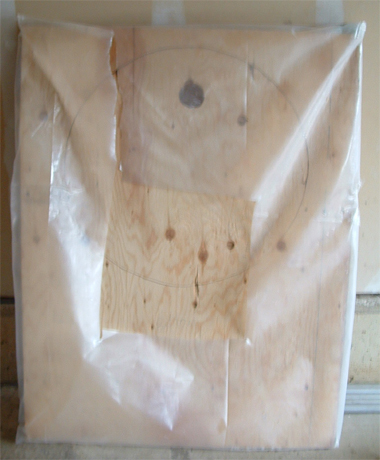
Just recently, I decided that I needed to make a new hovercraft that had better lift and real propulsion.
I started with a peice of 3′ x 4′ 1/2″ plywood. I cut a 24″ hole in the middle for my prop, and mounted the motor. The previous version had a leaf blower, but I figured that a prop would be better. This worked in the small test versions. Yet, after I had attached a good skirt and fired up the prop, it simply sat there, despite my prodding. I found that the model versions worked because the props spun very fast. Yet this version – a 24″ prop on a tractor starter motor – hardly acheived the same speed. Thus, my prop hoverfraft failed.
I wasn’t quite done yet though. I had designed my skirt much more efficiently than the previous version, hoping that I could use left energy for the lift fans. When I arrived at Mike’s house with this new version, we strapped on the leaf blower and gave it a run. It floated right out of the garage! Mike hopped on, and began cruising down the driveway. He probably reached 15 mph, until I heard a large POP then “Ahh!”. Apperently the un-reinforced skirt couldn’t take the pressure, and exploded.
As you can see, it ripped right up the corner. What’s was our answer to that issue, you ask? More Tape.
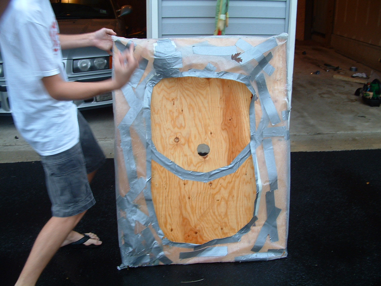
In the end with the tape, we took the hovercraft for a run in the pouring rain down a bit of a hill. This was quite interesting, becuase rooster tails of water and vapour came out both sides, and the ground behind was dry. But asphalt is abrasive, and we soon had more skirt holes. Perhaps this didn’t turn out to be the great project had originally hoped, but nonetheless it was quite entertaining.

Just recently, I decided that I needed to make a new hovercraft that had better lift and real propulsion.
I started with a peice of 3′ x 4′ 1/2″ plywood. I cut a 24″ hole in the middle for my prop, and mounted the motor. The previous version had a leaf blower, but I figured that a prop would be better. This worked in the small test versions. Yet, after I had attached a good skirt and fired up the prop, it simply sat there, despite my prodding. I found that the model versions worked because the props spun very fast. Yet this version – a 24″ prop on a tractor starter motor – hardly acheived the same speed. Thus, my prop hoverfraft failed.
I wasn’t quite done yet though. I had designed my skirt much more efficiently than the previous version, hoping that I could use left energy for the lift fans. When I arrived at Mike’s house with this new version, we strapped on the leaf blower and gave it a run. It floated right out of the garage! Mike hopped on, and began cruising down the driveway. He probably reached 15 mph, until I heard a large POP then “Ahh!”. Apperently the un-reinforced skirt couldn’t take the pressure, and exploded.
As you can see, it ripped right up the corner. What’s was our answer to that issue, you ask? More Tape.

In the end with the tape, we took the hovercraft for a run in the pouring rain down a bit of a hill. This was quite interesting, becuase rooster tails of water and vapour came out both sides, and the ground behind was dry. But asphalt is abrasive, and we soon had more skirt holes. Perhaps this didn’t turn out to be the great project had originally hoped, but nonetheless it was quite entertaining.
Friday, September 30. 2005
Sigh, the new hovercraft isn't floating
After a few nights of work, I had a hovercraft I was proud of. Beautifully crafted from plywood, a 2×4, and Visqueen, I was certain it would provide hours of hovering enjoyment.
Hah.
My test versions worked perfectly. I figured that the physics would scale up, and all would be great. Turns out, propellers don’t scale up. While the small versions would use the prop to hold air in the skirt, my 2-foot prop would simply let the pressure come right back out between the blades. This could be because the larger prop spins slower….. but nonetheless, it’s back to a leaf blower until I work this out.
Monday, September 26. 2005
New hovercraft is almost ready!
I recently whipped up some drawings for a easy-to-build two person hovercraft. I’m now in the buildling stage, and it’s nearing completion! I should be able to ferry 350 pounds around, using a 24″ propeller and a tractor starter motor for thrust.
Saturday, November 6. 2004
The Balancing Bot
I was looking around for a new project one day, when nBot caught my attention. I knew that balancing robots were hard (look how much the segway costs!), but the more I thought, the more I knew I had to try. [pics missing]
I am yet to have it balance indefinatly, at which point I will write a whole paper about doing this. However right now, I will just list the various versions, and how well they worked.
Version 1
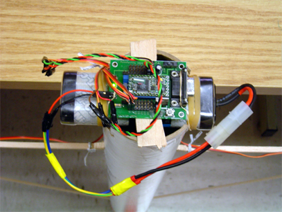
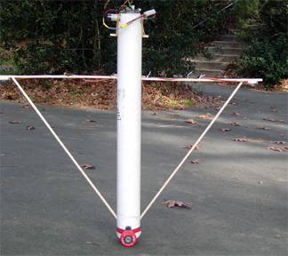
This was (obviously) the first version. It was about 4 feet tall. I found that my motors move way too slowly to keep a bot this size up. Thus we went to the next version.
Version 2
I chopped off about a foot and a half, so the bot is now 2 and a half feet. I figured that the bot would be able to right itself better since the moment arm is shorter, thus the same linear speed is a much faster angular speed. It now stands for about 10 seconds, but inevitably still falls.
Version 2.5
I found that the problems were due to inaccurate readings in the IR sensors. So I made a running array of the last 8 values, and used the average of them for the calulation. This didn’t quite work, either. Look at these graphs:
For both of these tests, the IR sensor was stationary in a vise pointed at a wall. That should give you some idead how inaccurate it is. The first is without my fix:

And with the fix:

Version 3
I gave up on the IR sensors: now I’m using sonar. It’s much more accurate, but I only have one. So the bot now balances for about 20 seconds, but the wheels simply can’t go fast enough to catch up if it gets moving more than a few inches per second. I hope to make some new wheels today.
Version 3.1
I ran over to the wood shop (we don’t have a metal shop) and made some bigger wheels… it seemed to me that the servos had quite a bit of torque, but didn’t go fast enough. Thus, increase the radius, we increase the distance traveled per revolution.
Version 4.0
The whole bot has been completly redesigned. The wheels of wood were not prefectly true, and thus wobbled way too much to balance properly. Also, the body was not ideal, the motors weren’t good enough, it was too tall, heavy in the wrong places….
This new bot has been designed completly in aluminum. (And crafted with nothing more than a jigsaw and a drill, plus some Erector set peices.) Yet still, it’s nicer than the previous models. It balanced nicely, has a large electric drill motor and sonar.
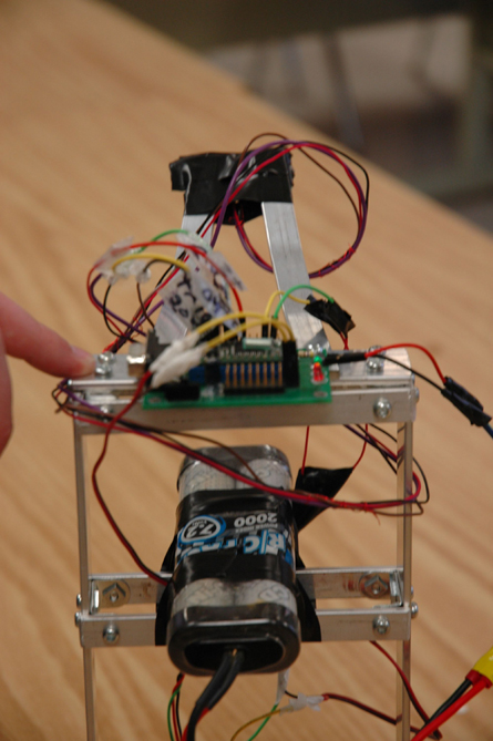
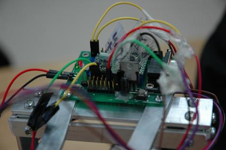
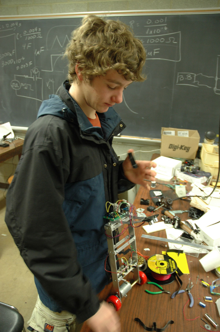
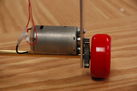
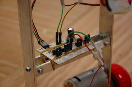
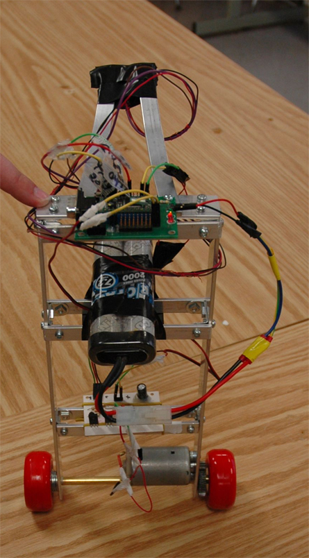
I am yet to have it balance indefinatly, at which point I will write a whole paper about doing this. However right now, I will just list the various versions, and how well they worked.
Version 1


This was (obviously) the first version. It was about 4 feet tall. I found that my motors move way too slowly to keep a bot this size up. Thus we went to the next version.
Version 2
I chopped off about a foot and a half, so the bot is now 2 and a half feet. I figured that the bot would be able to right itself better since the moment arm is shorter, thus the same linear speed is a much faster angular speed. It now stands for about 10 seconds, but inevitably still falls.
Version 2.5
I found that the problems were due to inaccurate readings in the IR sensors. So I made a running array of the last 8 values, and used the average of them for the calulation. This didn’t quite work, either. Look at these graphs:
For both of these tests, the IR sensor was stationary in a vise pointed at a wall. That should give you some idead how inaccurate it is. The first is without my fix:

And with the fix:

Version 3
I gave up on the IR sensors: now I’m using sonar. It’s much more accurate, but I only have one. So the bot now balances for about 20 seconds, but the wheels simply can’t go fast enough to catch up if it gets moving more than a few inches per second. I hope to make some new wheels today.
Version 3.1
I ran over to the wood shop (we don’t have a metal shop) and made some bigger wheels… it seemed to me that the servos had quite a bit of torque, but didn’t go fast enough. Thus, increase the radius, we increase the distance traveled per revolution.
Version 4.0
The whole bot has been completly redesigned. The wheels of wood were not prefectly true, and thus wobbled way too much to balance properly. Also, the body was not ideal, the motors weren’t good enough, it was too tall, heavy in the wrong places….
This new bot has been designed completly in aluminum. (And crafted with nothing more than a jigsaw and a drill, plus some Erector set peices.) Yet still, it’s nicer than the previous models. It balanced nicely, has a large electric drill motor and sonar.


Wednesday, September 22. 2004
The Trebuchet
After returning from Europe, I decided that medieval siege weapons were much cooler than those of today. A friend and I had previously built a (sort of) working trebuchet, but we could only launch one brick about 5 feet before the thing colapsed upon itself. However, with a new found interest, and a book of pictures, we went about designing a new and improved trebuchet. [pics missing]
Update: The Trebuchet made a new record of 234 feet, and at the same time broke! But I hear it’s all better. See the bottom of the page for the pictures of the damage.
Video One
Video Two
As you may have noticed, most of the projects on this site seem to have been made with as little money as possible. This was the case here. The original trebuchet (we’re now in the 3rd build) was crafted with a bucket and the duct tape, asagging too-small rod, etc. The 2×4′s in the boom and the stand happened to be the only so-called “professional” matterials in the whole project. The cross braces were wooden stakes, the cradle was an old feed bag, the rope was as far as I can tell from one of those cheap volley ball nets. But hey, it worked. The latest version, however, is a bit better. Real wood is used, as well as a very strong cross rod. Standing over 24 feet tall, it’s truly a work of art.
The principle of the trebuchet is simple: a weight on one end will make the other end lift, and inertia will cary whatever was there forward. It is much like a catapult, except that rather than storing energy in a bent tree, we store it in the process of lifting the weight up. The weight goes on the shorter end, so the other end swings faster. Our weight was a spackle bucket filled with rocks, coal, and water. (Don’t get the idea that coal is amazing for this purpose; my friend simply had some lying around.)
Though not attached in the picture, there is another peice that adds momentum to the launched object. The sling swings out from underneth during launch, thus adding more inertia. The hook (which the log is sitting on…. it works just to launch stuff by itself.) lets go of one side of the sling at just the right momment (theoretically) so that the object goes flying. We were unable to make our sling detach at the right momment, so we stuck stuff on the hook. However, this is an ongoing project, and it will work sometime soon.
Pictures (Click on any to get the full size!)
The first version! Pretty strange, eh?

The next version: 1.8

Version 2. Note the new side bracing:


Version 3! The final and coolest.

A nice view of V3:

And the moment you’ve been waiting for! These are the pics of the damage the took place during a record-breaking 243 foot launch.
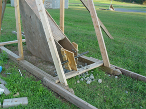


Despite a few setbacks, and a lack of good materials the first time, we still made this thing work! As I said, we will continue to work on it. Any crazy ideas, etc, make sure to drop a line by way of email or replies!
Update: The Trebuchet made a new record of 234 feet, and at the same time broke! But I hear it’s all better. See the bottom of the page for the pictures of the damage.
Video One
Video Two
As you may have noticed, most of the projects on this site seem to have been made with as little money as possible. This was the case here. The original trebuchet (we’re now in the 3rd build) was crafted with a bucket and the duct tape, asagging too-small rod, etc. The 2×4′s in the boom and the stand happened to be the only so-called “professional” matterials in the whole project. The cross braces were wooden stakes, the cradle was an old feed bag, the rope was as far as I can tell from one of those cheap volley ball nets. But hey, it worked. The latest version, however, is a bit better. Real wood is used, as well as a very strong cross rod. Standing over 24 feet tall, it’s truly a work of art.
The principle of the trebuchet is simple: a weight on one end will make the other end lift, and inertia will cary whatever was there forward. It is much like a catapult, except that rather than storing energy in a bent tree, we store it in the process of lifting the weight up. The weight goes on the shorter end, so the other end swings faster. Our weight was a spackle bucket filled with rocks, coal, and water. (Don’t get the idea that coal is amazing for this purpose; my friend simply had some lying around.)
Though not attached in the picture, there is another peice that adds momentum to the launched object. The sling swings out from underneth during launch, thus adding more inertia. The hook (which the log is sitting on…. it works just to launch stuff by itself.) lets go of one side of the sling at just the right momment (theoretically) so that the object goes flying. We were unable to make our sling detach at the right momment, so we stuck stuff on the hook. However, this is an ongoing project, and it will work sometime soon.
Pictures (Click on any to get the full size!)
The first version! Pretty strange, eh?

The next version: 1.8

Version 2. Note the new side bracing:


Version 3! The final and coolest.

A nice view of V3:

And the moment you’ve been waiting for! These are the pics of the damage the took place during a record-breaking 243 foot launch.


Despite a few setbacks, and a lack of good materials the first time, we still made this thing work! As I said, we will continue to work on it. Any crazy ideas, etc, make sure to drop a line by way of email or replies!
Monday, September 13. 2004
Trebuchet gone out with a blast
I’ve just gotten news that the trebuchet went out in glory. It both made a new record (243 ft) and broke appart at the same time. Though I was not there to witness the event, I will receive pictures and perhaps video shortly, and post them. See the trebuchet article here.
Update: After posting the above, the other trebuchet man (Mike) send the following: “‘Out in Glory’? I don’t think so Jack, the trebuchet is still standing strong. It will yet again be laying seige to the neighbor’s driveway by the end of the week!”
Update: After posting the above, the other trebuchet man (Mike) send the following: “‘Out in Glory’? I don’t think so Jack, the trebuchet is still standing strong. It will yet again be laying seige to the neighbor’s driveway by the end of the week!”
(Page 1 of 1, totaling 13 entries)
Email me:
jack {@} crepinc.com
Recent Projects:
Analog HF Transmitter
Audi ECU Reverse Engineering
Dual DAC QAM Modulator
FPGA QAM Modulator
Geiger Counter
Gyro-Stabilized DSLR Platform
Hybrid Rocket Engines
Turbocharger Controller
WWVB Rx and Tx
Older Projects:
Balancing Bot
Capacitor Array
CNC Mill
DCIR Renderer
Electric Gokart
Hovercraft
Low Alt. Temp. Model
Shopping Cart Locker
Trebuchet
My Twitter occasionally shows projects I'm working on.
My GitHub has code from a few projects on it.