Wednesday, May 14. 2014
Interfacing Cirrus Logic Audio ADCs
I've been considering ideas for audio gear of various sorts over the past few months, and decided a good starting place would be a solid ADC interface from which I could prototype concepts. Lots of companies make audio converters, but I settled on two models from Cirrus Logic: the CS5361 and CS5340. They are, respectively, balanced and unbalanced two-channel 24-bit 192 khz high dynamic range delta-sigma oversampling devices.
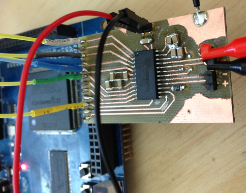
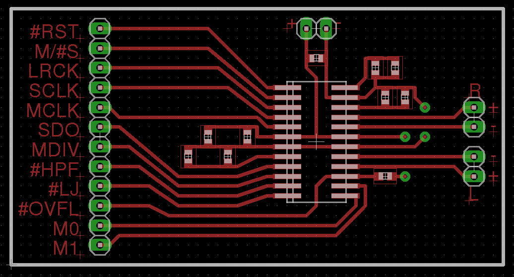
I started by laying out a super-simple protoboard for the CS5361. Since I wanted this to be quick and easy to cut on the CNC mill, the board is single-sided with the bare minimum of filtering, and without standard mixed signal board design concepts like separate analog and digital ground planes. While this will negatively affect the noise figure a bit, I wanted to get the device up and running with the minimum investment of time in case my assumptions regarding its usage and support were incorrect.

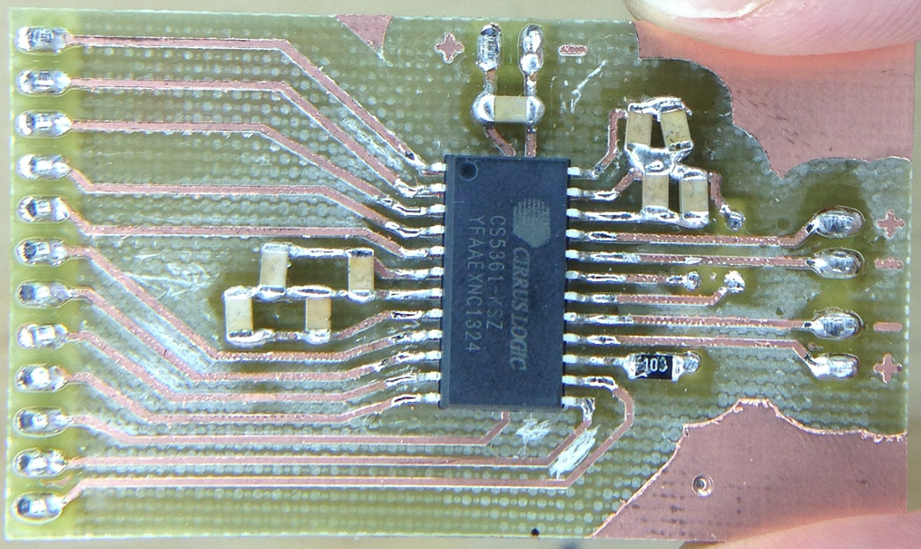
By the time I had finished the layout and cut the board, the samples order had arrived! Soldering was quick though a tad arduous - I need to use a larger 1206 footprint next time.

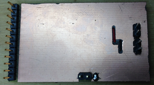
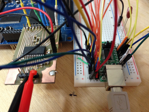
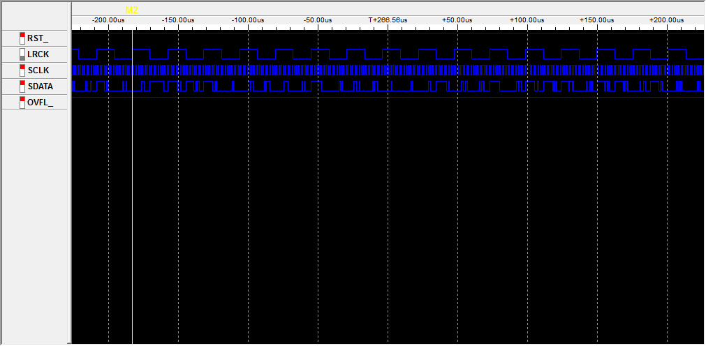
My ugly solder job notwithstanding, I plugged the unit into a breadboard, wired up an oscillator, config pins, and the logic analyzer, and was immediately rewarded with correct operation:
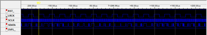
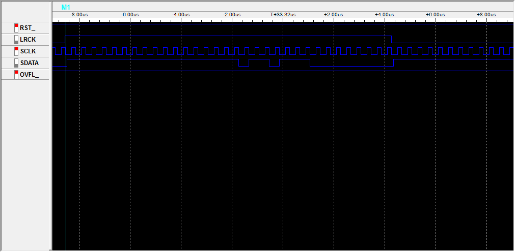
In short, by simply applying power, config pin states, and a master clock, the device will shift out ADC values (in 2's compliment form) msb-first on the falling edge of SCLK (ie, we sample on the rising edge):

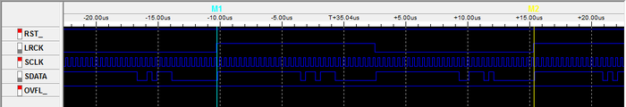
The only other line we need to worry about is LRCK, which indicates the channel being sent - you can see here that we get a left sample, then a right sample, then repeat:
With the hardware working, I set about writing the Verilog modules to nab samples from the ADC and send them off via USB (using an FT245R FIFO interface I have on hand). The code is extremely simple: on the rising edge of SCLK, samples are shifted into an 8-bit register - the size of the data bus on the USB interface. Every 8 bits, that register is strobed into the FT245R and the process repeats.
Byte alignment is provided by LRCK: on a start or reset condition from the USB host, the FPGA waits for a rising edge of LRCK before beginning the sampling and transmission of samples. This allows the client end to interpret the data stream without framing bytes: incoming data is simply shifted into 3-byte (24-bit) samples, left then right, and processed as desired.
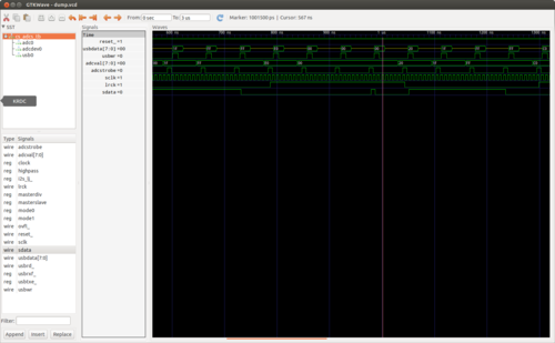
The code was quick to write and simulate with my favorite tools, iVerilog and GTKWave. I implemented a quick CS5361 module whose left and right channels count up and down (respectively) so as to simulate the rest of the pieces. Unfortunately I spent almost as much time debugging the code in hardware with the logic analyzer as I did writing the code, as Quartus (the Altera design software) is rather inconsistent in its handling of constants and register widths. (note: always read every line of output from the Altera synthesis toolchain - one can easily spend 4 hours trying to debug a problem that makes no sense only to find that the synthesis tool decided a constant was the wrong size and used zero instead)
In any event, I did manage to squash the few Quartus oddities that had caused the hardware to operate differently from the simulated code, and verified that the USB interface looked correct using the logic analyzer. Time for more spaghetti:
Time to test it out. In its current state, the FPGA will assert a reset condition on any received byte from the FIFO buffer. So, we will send a reset byte then read 24 samples of 6 bytes (3 for each channel):
root@ichor ~ # echo -n 0 > /dev/ttyUSB0 && dd if=/dev/ttyUSB0 count=24 bs=6 2>/dev/null | hexdump
0000000 3238 a13f 4a68 a650 0344 bd41 6632 ceaa
0000010 78f2 28f8 9764 19ca 7185 45b4 6bfd eabf
0000020 9825 8050 65e5 6122 3adc 0830 28f0 9dfc
0000030 d026 746a e2c0 befa 57dc 1fa4 4225 7b82
0000040 a61b ed00 2320 d641 e111 b648 a2f3 8d3a
0000050 bdfb afb6 1287 5963 ff57 9c8e 63a1 3971
0000060 4bfe ac6e 5081 9fae 2b0d 5c4c 6eaa 26b7
0000070 164b 6093 8378 96d8 138c 160e e661 a81b
0000080 81bc bdae 530b ec79 3537 6ada b0cc 4773
0000090
Success! With that working, the next steps are to implement the CS5340 and add proper dynamic configuration loading. From there, I am hoping to implement ADAT input and output and a simple device driver to interface the kernel audio subsystem.
I've put the code, board design, and a bit of documentation on GitHub: jackcarrozzo/cs_adcs.
I started by laying out a super-simple protoboard for the CS5361. Since I wanted this to be quick and easy to cut on the CNC mill, the board is single-sided with the bare minimum of filtering, and without standard mixed signal board design concepts like separate analog and digital ground planes. While this will negatively affect the noise figure a bit, I wanted to get the device up and running with the minimum investment of time in case my assumptions regarding its usage and support were incorrect.
By the time I had finished the layout and cut the board, the samples order had arrived! Soldering was quick though a tad arduous - I need to use a larger 1206 footprint next time.

My ugly solder job notwithstanding, I plugged the unit into a breadboard, wired up an oscillator, config pins, and the logic analyzer, and was immediately rewarded with correct operation:
In short, by simply applying power, config pin states, and a master clock, the device will shift out ADC values (in 2's compliment form) msb-first on the falling edge of SCLK (ie, we sample on the rising edge):
The only other line we need to worry about is LRCK, which indicates the channel being sent - you can see here that we get a left sample, then a right sample, then repeat:

With the hardware working, I set about writing the Verilog modules to nab samples from the ADC and send them off via USB (using an FT245R FIFO interface I have on hand). The code is extremely simple: on the rising edge of SCLK, samples are shifted into an 8-bit register - the size of the data bus on the USB interface. Every 8 bits, that register is strobed into the FT245R and the process repeats.
Byte alignment is provided by LRCK: on a start or reset condition from the USB host, the FPGA waits for a rising edge of LRCK before beginning the sampling and transmission of samples. This allows the client end to interpret the data stream without framing bytes: incoming data is simply shifted into 3-byte (24-bit) samples, left then right, and processed as desired.

The code was quick to write and simulate with my favorite tools, iVerilog and GTKWave. I implemented a quick CS5361 module whose left and right channels count up and down (respectively) so as to simulate the rest of the pieces. Unfortunately I spent almost as much time debugging the code in hardware with the logic analyzer as I did writing the code, as Quartus (the Altera design software) is rather inconsistent in its handling of constants and register widths. (note: always read every line of output from the Altera synthesis toolchain - one can easily spend 4 hours trying to debug a problem that makes no sense only to find that the synthesis tool decided a constant was the wrong size and used zero instead)

In any event, I did manage to squash the few Quartus oddities that had caused the hardware to operate differently from the simulated code, and verified that the USB interface looked correct using the logic analyzer. Time for more spaghetti:

Time to test it out. In its current state, the FPGA will assert a reset condition on any received byte from the FIFO buffer. So, we will send a reset byte then read 24 samples of 6 bytes (3 for each channel):
root@ichor ~ # echo -n 0 > /dev/ttyUSB0 && dd if=/dev/ttyUSB0 count=24 bs=6 2>/dev/null | hexdump
0000000 3238 a13f 4a68 a650 0344 bd41 6632 ceaa
0000010 78f2 28f8 9764 19ca 7185 45b4 6bfd eabf
0000020 9825 8050 65e5 6122 3adc 0830 28f0 9dfc
0000030 d026 746a e2c0 befa 57dc 1fa4 4225 7b82
0000040 a61b ed00 2320 d641 e111 b648 a2f3 8d3a
0000050 bdfb afb6 1287 5963 ff57 9c8e 63a1 3971
0000060 4bfe ac6e 5081 9fae 2b0d 5c4c 6eaa 26b7
0000070 164b 6093 8378 96d8 138c 160e e661 a81b
0000080 81bc bdae 530b ec79 3537 6ada b0cc 4773
0000090
Success! With that working, the next steps are to implement the CS5340 and add proper dynamic configuration loading. From there, I am hoping to implement ADAT input and output and a simple device driver to interface the kernel audio subsystem.
I've put the code, board design, and a bit of documentation on GitHub: jackcarrozzo/cs_adcs.
Thursday, February 20. 2014
WWVB Receiver and Testing Transmitter
As I've been making steady progress on my Z80 computer, I've put a lot of thought into something to actually do with it when it's done. As tempting as it is to load up CP/M, add a video interface, and use it as my main machine, I think porting Firefox is too ambitious. For now, I've decided to add some more 7-segment displays and an RF front end to decode the WWVB time signal from an atomic clock in Colorado and hang it on the wall. If I'm still feeling ambitious, I'll add an Ethernet controller and write a driver and NTP daemon for it. Of course, this means I need a working receiver front end for 60kHz.

The WWVB signal is quite simple as far as decoding goes: the carrier has "full power" and "low power" states. The transmitter drops the carrier by 17 dB at the start of each second, and the length of time before it returns provides a single trinary value: Mark (0.8s), Not Set (0.2s), or Set (0.5s). A single digital line that goes low or high to follow the transmitter power state is quite easy to achieve with a fully analog circuit: after a bandpass to select only the 60kHz carrier, we send the signal into two peak detectors - one with a long time constant (low pass filter) to track the average signal power over several seconds, and one with a shorter time constant to track the per-second changes. Passing these two signals to a comparator, we get our nice single-bit TTL indicator of the current signal state. Plus, the longer time constant peak detector acts as an auto gain control, so no alignment is required.

While I will make my own receiver as described above for the final version, I ordered a SYM-RFT module for testing. It includes an LED to indicate received carrier status and outputs the inverted carrier power state compared to the average carrier power. I quickly breadboarded it up to an FT245R USB chip and wrote a few lines of C to poll the power status and measure the length of state changes. Unfortunately, New England being quite far from Colorado, the signal is below the noise floor and has thus far been highly unreliable. The module simply flashes chaotically in the presence of any electronic noise like my monitors, and does nothing in isolation.
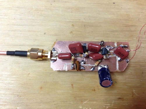
I built the above two-stage preamp from two 2N3904's to attach to the 60kHz antenna that came with the SYM-RFT module to see if I could see any carrier on the oscilloscope. While I did get all sorts of noise and impulses, there was very little if any energy at 60kHz. Drat.
Luckily, I have the tools on hand to recreate the signal so I can at least test my receiver and code. I pulled out the FPGA RF DAC board I put together a while back, and a page of Verilog later I had a compliant WWVB transmitter:
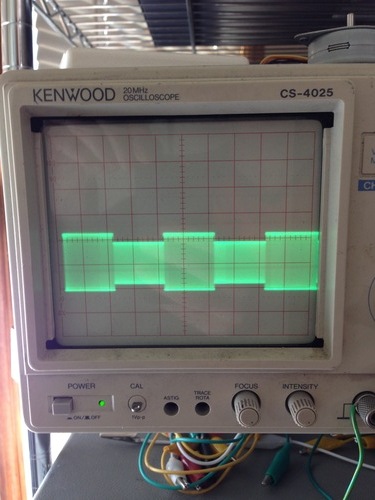
After a small battle with PLLs to get a slow enough clock for 60khz, both the SYM-RFT and my USB worked fine.
jackc@ichor ~/Projects/wwvb_usb $ sudo ./wwvb
MARK : 950 ms
NOT SET : 239 ms
SET : 503 ms
NOT SET : 194 ms
SET : 581 ms
MARK : 991 ms
^Cjackc@ichor ~/Projects/wwvb_usb $
The WWVB signal is quite simple as far as decoding goes: the carrier has "full power" and "low power" states. The transmitter drops the carrier by 17 dB at the start of each second, and the length of time before it returns provides a single trinary value: Mark (0.8s), Not Set (0.2s), or Set (0.5s). A single digital line that goes low or high to follow the transmitter power state is quite easy to achieve with a fully analog circuit: after a bandpass to select only the 60kHz carrier, we send the signal into two peak detectors - one with a long time constant (low pass filter) to track the average signal power over several seconds, and one with a shorter time constant to track the per-second changes. Passing these two signals to a comparator, we get our nice single-bit TTL indicator of the current signal state. Plus, the longer time constant peak detector acts as an auto gain control, so no alignment is required.
While I will make my own receiver as described above for the final version, I ordered a SYM-RFT module for testing. It includes an LED to indicate received carrier status and outputs the inverted carrier power state compared to the average carrier power. I quickly breadboarded it up to an FT245R USB chip and wrote a few lines of C to poll the power status and measure the length of state changes. Unfortunately, New England being quite far from Colorado, the signal is below the noise floor and has thus far been highly unreliable. The module simply flashes chaotically in the presence of any electronic noise like my monitors, and does nothing in isolation.
I built the above two-stage preamp from two 2N3904's to attach to the 60kHz antenna that came with the SYM-RFT module to see if I could see any carrier on the oscilloscope. While I did get all sorts of noise and impulses, there was very little if any energy at 60kHz. Drat.
Luckily, I have the tools on hand to recreate the signal so I can at least test my receiver and code. I pulled out the FPGA RF DAC board I put together a while back, and a page of Verilog later I had a compliant WWVB transmitter:
After a small battle with PLLs to get a slow enough clock for 60khz, both the SYM-RFT and my USB worked fine.
jackc@ichor ~/Projects/wwvb_usb $ sudo ./wwvb
MARK : 950 ms
NOT SET : 239 ms
SET : 503 ms
NOT SET : 194 ms
SET : 581 ms
MARK : 991 ms
^Cjackc@ichor ~/Projects/wwvb_usb $
Wednesday, August 21. 2013
Geiger Counter
I haven't done a whole lot of analog or power supply design, so I thought it'd be an interesting project to build a simple Geiger counter. In theory, their operation is very simple: provide ~500 vdc to the tube, and incoming particles will ionize the gas inside long enough to change the impedance of the tube, which we measure with a high-pass filter.
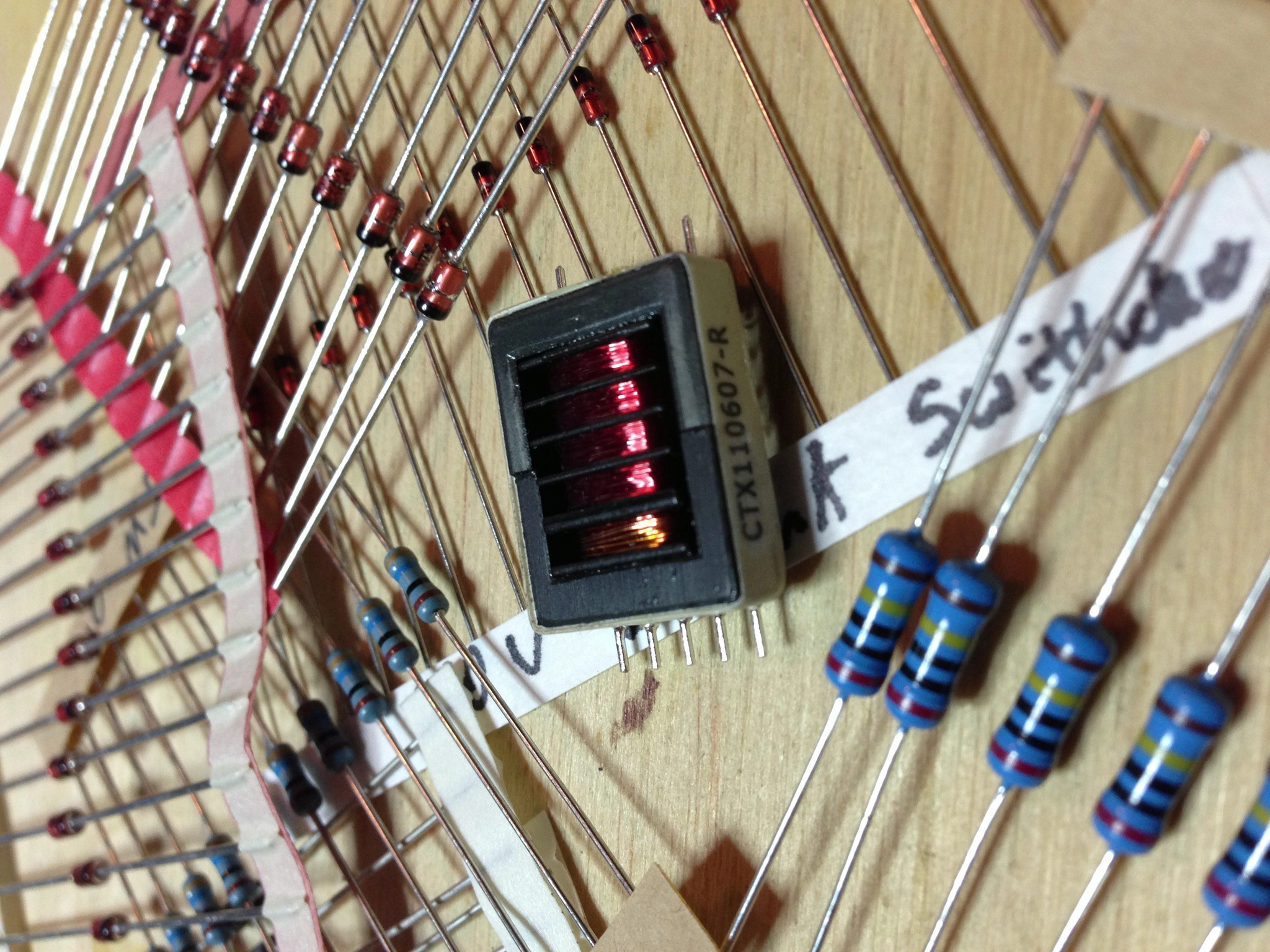
To create 500 volts from a 9v input (I'd like it to be portable), I used a 555 timer at 1khz to gate two 2n222 NPN transistors ground-side switching the input to the transformer. I tried a few HV transformers I had in the junk bin, but nothing was quite right, so I ordered a few CTX110607-R's which performed splendidly.
From the output of the transformer, we go through two stages of voltage doubler (the last one acting as a rectifier and low pass filter), and voltage regulation is provided by two 200v zeniers and one 100v zenier.
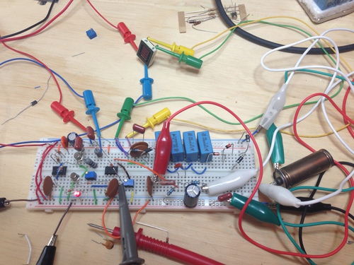
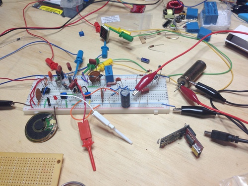
The signal is separated from the HV rails by a 50pf capacitor, which then goes to a comparator with one more filter between its two stages. This let me use a fast high-pass and a peak detector, as opposed to a single slow-enough-to-see-and-hear high-pass filter.
After I confirmed my design with the mess on my desk, I soldered up a final version:
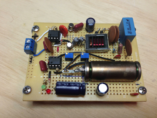
To create 500 volts from a 9v input (I'd like it to be portable), I used a 555 timer at 1khz to gate two 2n222 NPN transistors ground-side switching the input to the transformer. I tried a few HV transformers I had in the junk bin, but nothing was quite right, so I ordered a few CTX110607-R's which performed splendidly.
From the output of the transformer, we go through two stages of voltage doubler (the last one acting as a rectifier and low pass filter), and voltage regulation is provided by two 200v zeniers and one 100v zenier.

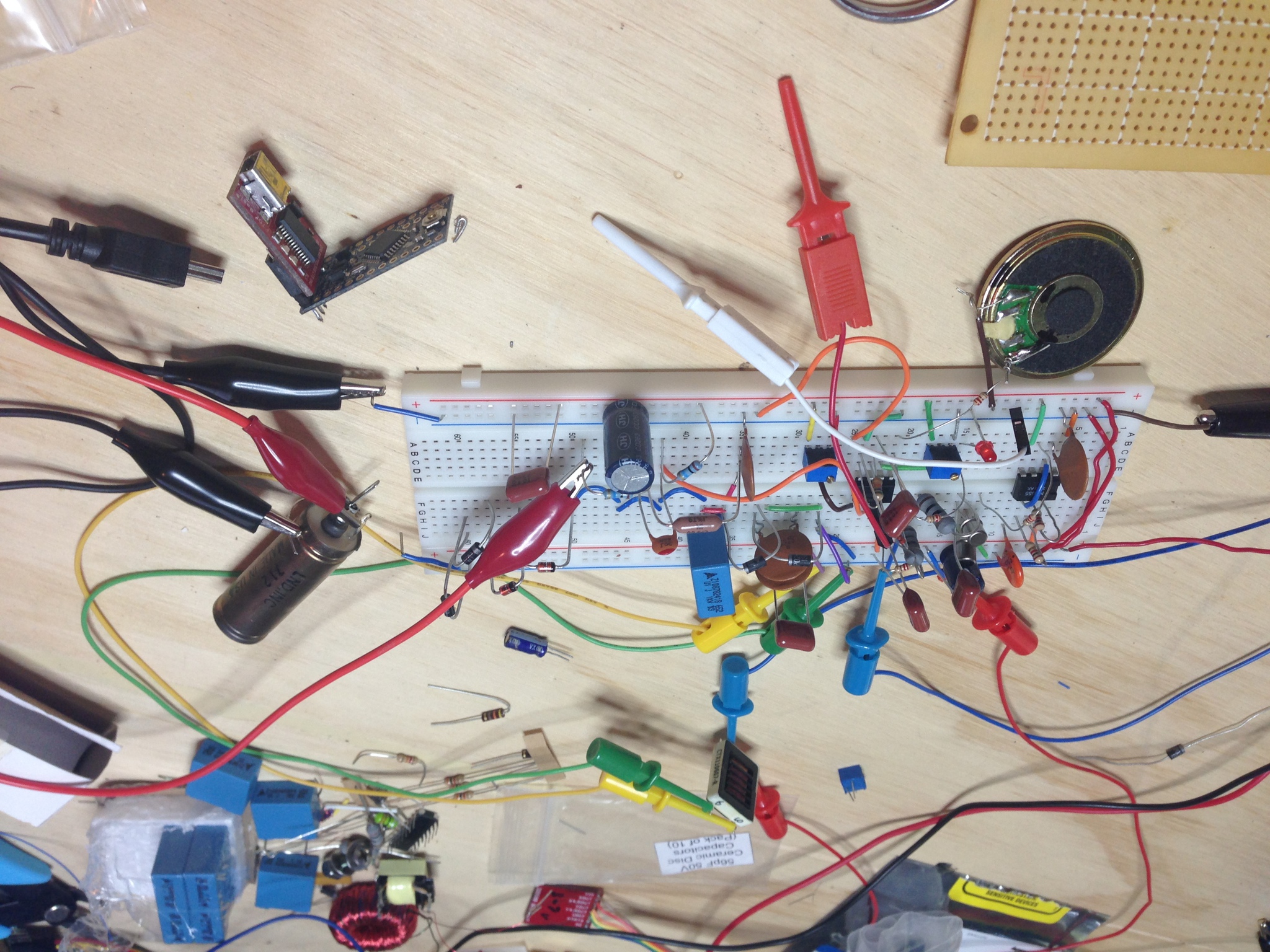
The signal is separated from the HV rails by a 50pf capacitor, which then goes to a comparator with one more filter between its two stages. This let me use a fast high-pass and a peak detector, as opposed to a single slow-enough-to-see-and-hear high-pass filter.
After I confirmed my design with the mess on my desk, I soldered up a final version:

Wednesday, February 20. 2013
All-Analog HF Transmitter
I'm going to Puerto Rico soon, and it just so happens we're staying on a beach facing the continental US. Since we won't have internet nor cell service while there, I thought it'd be fun to send tweets via HF as it would be a good excuse to building some simple analog radios. If I use slow synchronous CW driven and detected by FTDI dev boards and a few lines of C, all I need to do is hack up the radios themselves.
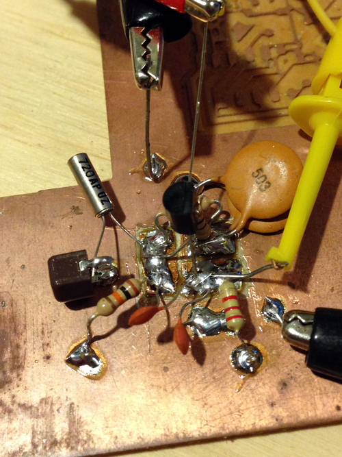
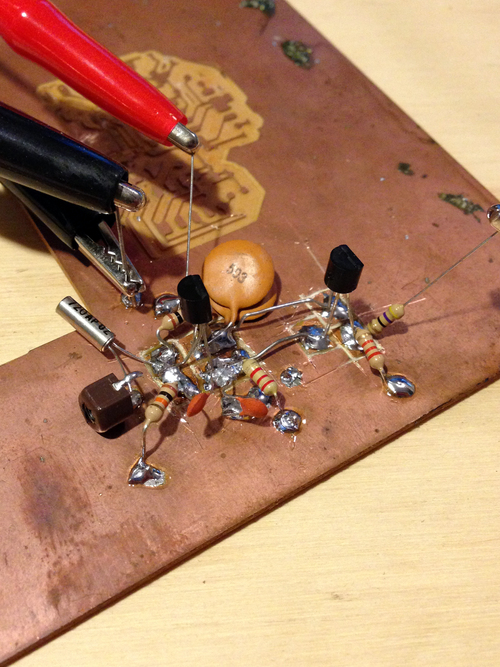
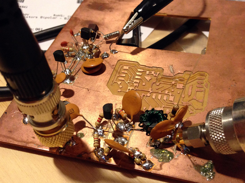
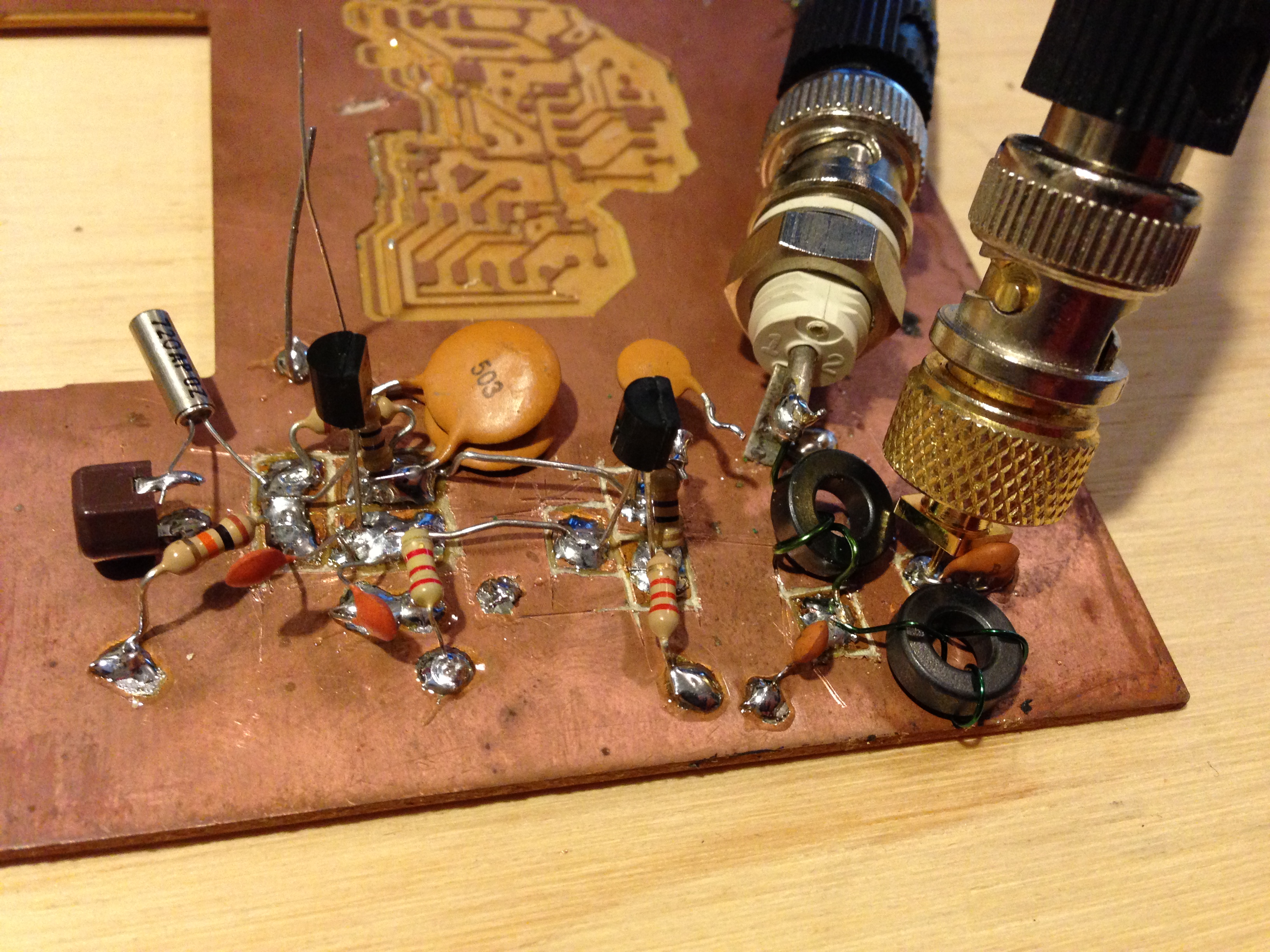
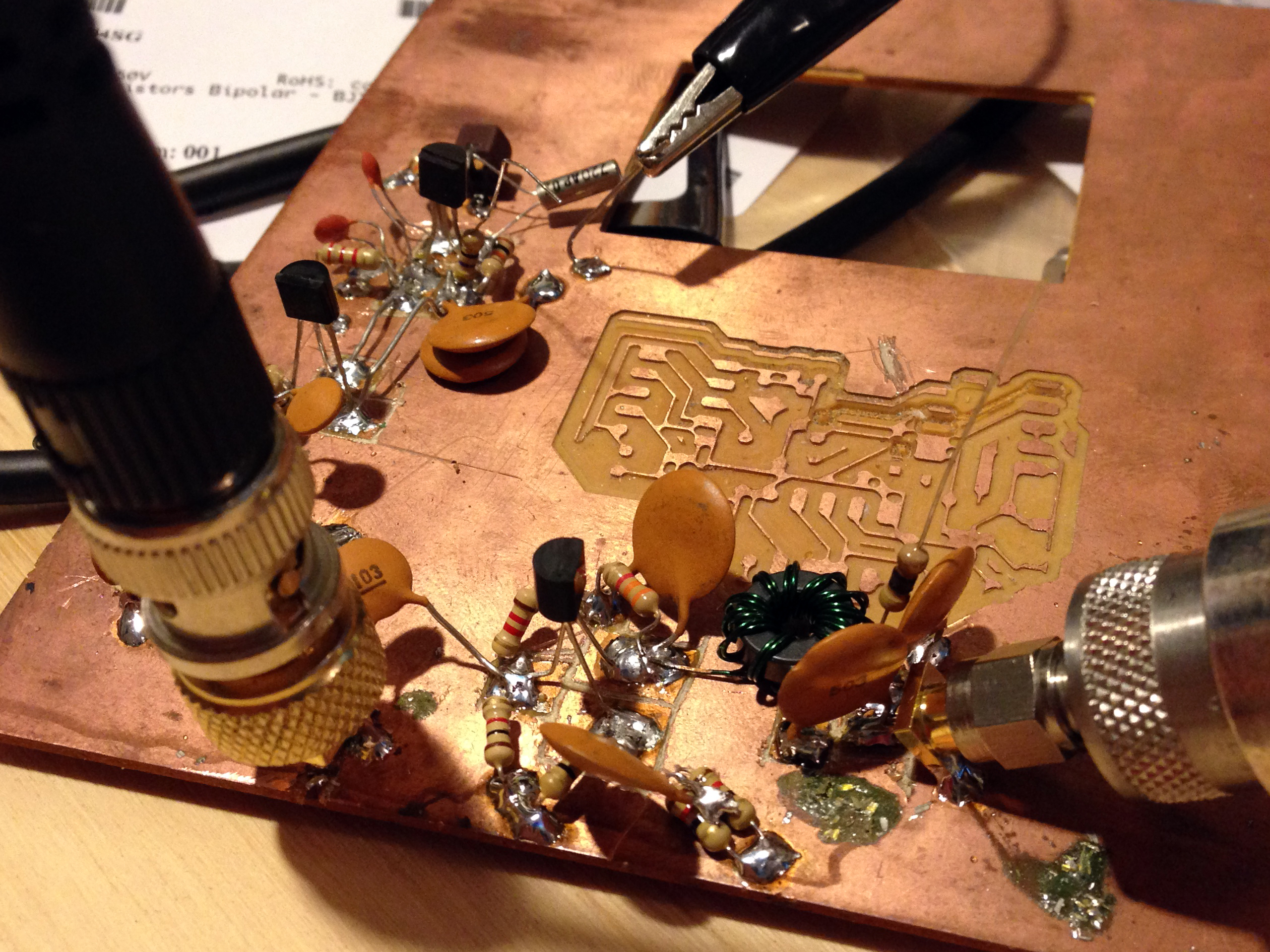
Starting at the TX end, I nabbed a gross piece of PCB from the pile and went to town dead-bugging the transmit chain. Yes, it looks like crap, but if it works as planned I'll design a proper board and cut it on the CNC mill. First I added the crystal oscillator, then its output buffer:
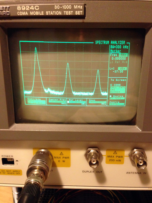
Nice! We can see from the spectrum analyzer that we are indeed getting waves, albeit with some fairly serious harmonics. Now to add a low pass filter:


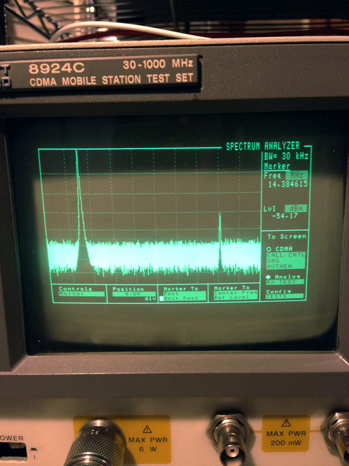
In the first image, you can see that I added connectors between the previous stage's output and the filter's input so I can sweep the filter independently. In the next image, you can see the filter's response on the spectrum analyzer with the tracking generator providing a flat source. Finally, the last image shows our frequency response of the whole system (osc, buffer driver, and filter) - the filter successfully brought the first harmonic down to -54 dBc. Time to add another gain stage and filter:
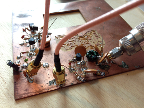
In the first pic, I'm again using the tracking generator to sweep only the response of this amplifier and filter (note that I removed the BNC connector I tacked onto the input of the first filter, and connected it directly to the output of the osc buffer). In the second, the whole chain is hooked up end-to-end. It's putting out 27 dBm (1/2W) at ~7.2 MHz, but the last amplifier transistor get warm quickly - looks like I'm going to need to replace that with something beefier.
Update: Unfortunately I got wicked busy with work prior to leaving for PR and wasn't able to finish this. I do hope to pick it up again soon...
Starting at the TX end, I nabbed a gross piece of PCB from the pile and went to town dead-bugging the transmit chain. Yes, it looks like crap, but if it works as planned I'll design a proper board and cut it on the CNC mill. First I added the crystal oscillator, then its output buffer:


Nice! We can see from the spectrum analyzer that we are indeed getting waves, albeit with some fairly serious harmonics. Now to add a low pass filter:
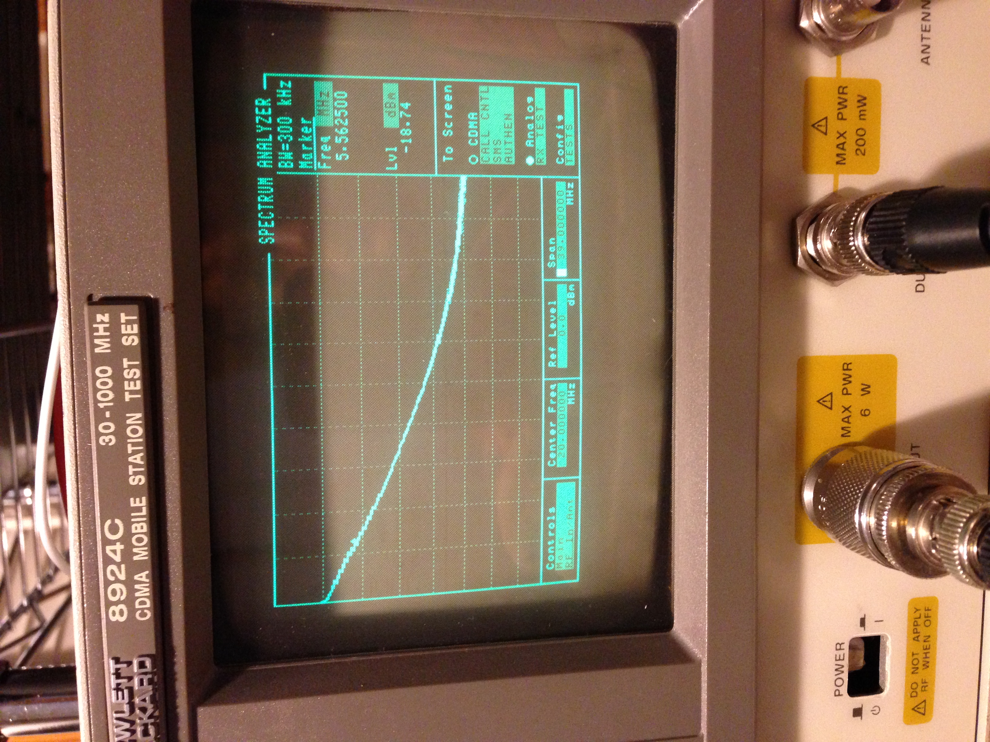

In the first image, you can see that I added connectors between the previous stage's output and the filter's input so I can sweep the filter independently. In the next image, you can see the filter's response on the spectrum analyzer with the tracking generator providing a flat source. Finally, the last image shows our frequency response of the whole system (osc, buffer driver, and filter) - the filter successfully brought the first harmonic down to -54 dBc. Time to add another gain stage and filter:

In the first pic, I'm again using the tracking generator to sweep only the response of this amplifier and filter (note that I removed the BNC connector I tacked onto the input of the first filter, and connected it directly to the output of the osc buffer). In the second, the whole chain is hooked up end-to-end. It's putting out 27 dBm (1/2W) at ~7.2 MHz, but the last amplifier transistor get warm quickly - looks like I'm going to need to replace that with something beefier.
Update: Unfortunately I got wicked busy with work prior to leaving for PR and wasn't able to finish this. I do hope to pick it up again soon...
Wednesday, November 14. 2007
Capacitor Array
Tuesday, November 28. 2006
H4x0ring Price Chopper
Forewarning: I may or may not have participated in any of the events listed herein. This may be pure fiction, take from it what you will. That said, it was pretty awsome…
If you’ve ever been to a supermarket in a city (like Worcester), you’ll have likely noticed a locking mechanism on one of the front wheels. It’s designed to lock the cart so that it won’t roll when you try to take it off the lot, so that people don’t steal them.
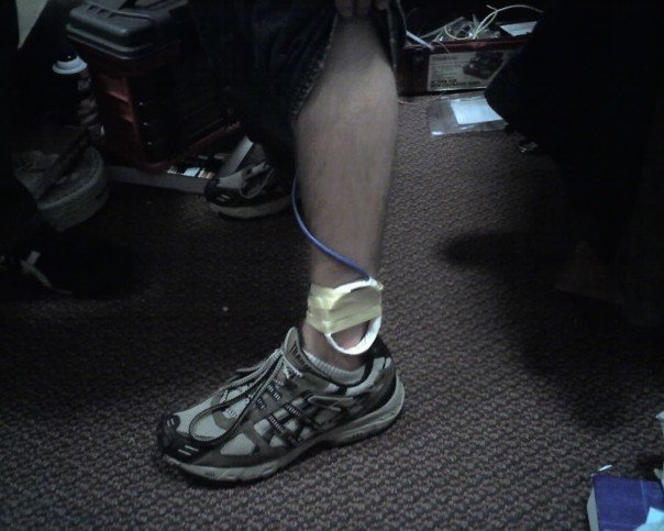
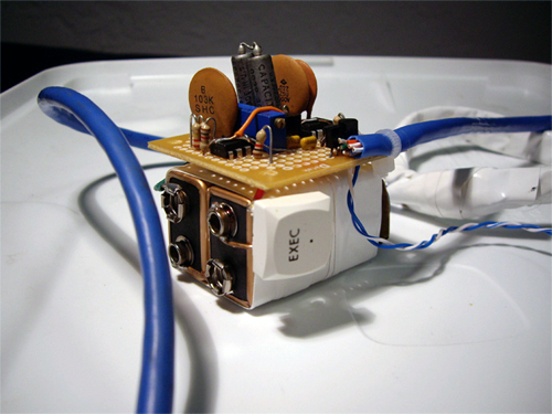
Around the perimeter of the parking lot, there is a wire acting as an antenna, transmitting an 8 khz square wave gated at 30 ms. This is the locking function. Using two LM555 timers, a few capacitors and resistors, and a coil of wire, a friend and I made our own transmitter.
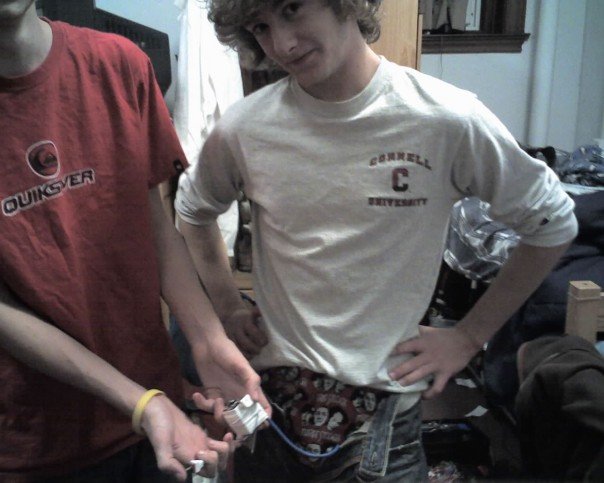
The transmitter was in my pocket with two switches: to select between lock and unlock, and to active the coil. Since the coil was down at my ancle, this waranted a wire up my pants.
We headed down to the supermarket in the middle of the night, and walked past a line of carts outside: click click click click click click click. They were all locked. The transmitter worked the first time.
We went inside and locked a few carts while they were moving as well, which obivously confused the people moving them.
If you’ve ever been to a supermarket in a city, you’ll have likely seen a lock on one of the front wheels of the carts to prevent people from stealing them. A friend and I managed to make a transmitter so that we could the carts would lock when I walked by with the transmitter in my pants.
If you’ve ever been to a supermarket in a city (like Worcester), you’ll have likely noticed a locking mechanism on one of the front wheels. It’s designed to lock the cart so that it won’t roll when you try to take it off the lot, so that people don’t steal them.
Around the perimeter of the parking lot, there is a wire acting as an antenna, transmitting an 8 khz square wave gated at 30 ms. This is the locking function. Using two LM555 timers, a few capacitors and resistors, and a coil of wire, a friend and I made our own transmitter.
The transmitter was in my pocket with two switches: to select between lock and unlock, and to active the coil. Since the coil was down at my ancle, this waranted a wire up my pants.
We headed down to the supermarket in the middle of the night, and walked past a line of carts outside: click click click click click click click. They were all locked. The transmitter worked the first time.
We went inside and locked a few carts while they were moving as well, which obivously confused the people moving them.
If you’ve ever been to a supermarket in a city, you’ll have likely seen a lock on one of the front wheels of the carts to prevent people from stealing them. A friend and I managed to make a transmitter so that we could the carts would lock when I walked by with the transmitter in my pants.
Thursday, April 27. 2006
Electric Gokart
Update: Now that I actually know how to machine things, I’m going to revamp the Kart next time I’m home. Real bearings for the steering assembly, pedals and a floorboard, etc. Should be interesting…
I built this “Kart” basically because I wanted to see if I was good at building large (or larger than normal) things, and to satisfy a “project” requirment for my physics class. While most people built small electronics projects on breadboards, I built this. People were pretty surprised.
Update to the update: The frame got turned into a trike for the hang glider, and the motor got imported to a scooter. Both were epic.
Frame
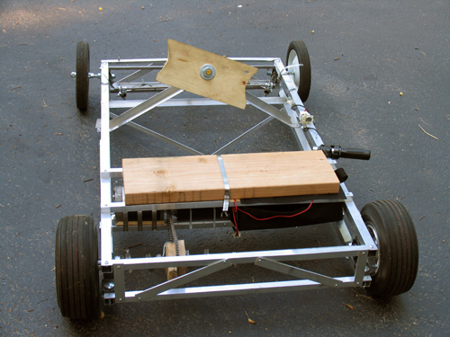
The frame was designed (in my head, since I can’t draw) to be very light, but hopefully still fairly strong. Four 1″ square aluminum stock bars run the length of the frame as 4 edges of a box. Each side of this “box” is then held the proper distance apart by perpendicular flat stock and held rigid by 2 opposite-direction diagnals of either flat stock or square stock.
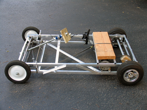
The cross peices that go between the frame sides in the front are 1/2″ inch steel square stock. It is absolutly key that these side sections stay the same distance apart, as they control the cambre of the wheels. The steel is held in place by threaded rod. (I would have used aluminum, but Home Depot is terrible at restocking and never had enough.)
The front wheels are lame garden wheels from Home Depot (about $8 each) with built in bearings. It remains to be seen how long the bearings will last, but they haven’t fallen out yet…
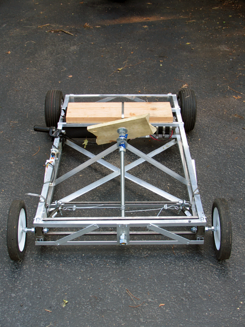
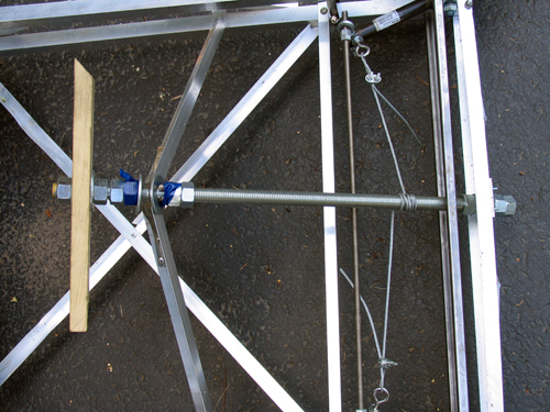
Steering
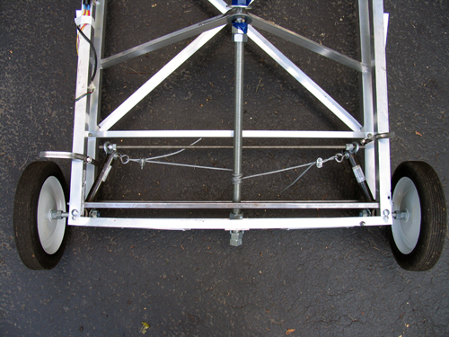
The steering idea was conceived by Sean Manix and Joe Gage in a gravity-powered car we built long ago. I modified the design somewhat to work here. Basically, the system works as a rack and pinion system does, minus the rack and the pinion. The tierod keeps outward tension on the steering arms so that they stay the proper distance apart and the wheels stay parallel; the wire pulls the whole sytem to one side or the other to steer while at the same time keeping tension on the steering arms so they stay on the tierod.
Yes, the steering arms are made of plumbing equipment.
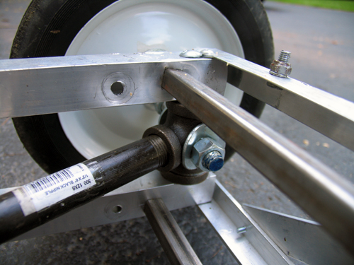
Inside those plumbing T’s, bolts come in from both square sections of frame. Roller skate bearings (that I had around and just happened to fit) go over the bolts and space the plumbing to sit in the center. I then put the T’s on the drill press and put the 1/2″ holes in them. Let me tell you, that was scary. The bit has a tendancy to catch coming out the other side, so the whole T arm unit spins around the bit fast enough to break your arm.
As inaccurate as this looks, it actual is very smooth and tight. The steering feels nice while youre driving.
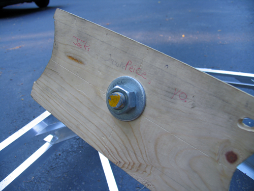
…don’t ask, it’s a school thing somebody wrote. But yes, that is the “steering plank”.
Drive Train
The motor is from an electric scooter. It’s 750 Watts… in pure energy, 1 horsepower = 746 Watts, but I think here the 750w describe amount of power the motor pulls from the batteries, not the mechanical energy put out. Since the motor is likely only moderatly efficient, I’d say it’s in the half-horsepower range.
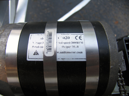
My girlfriend Erica is building a kart on the same design as this one. I helped her get her motor… hers is 1200w. I think I’ll still be able to beat her once I figure out how to put some sort of transmission on this thing. The chain and rear cog are from the scooter too.
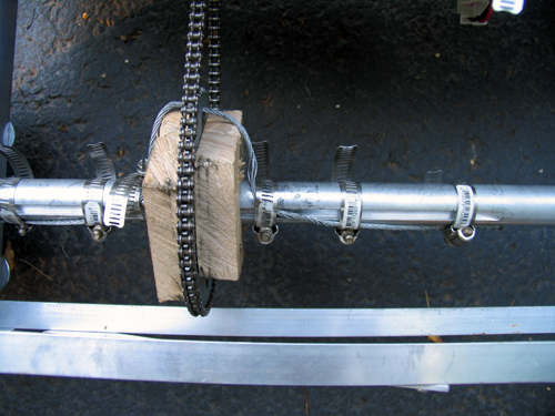
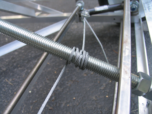
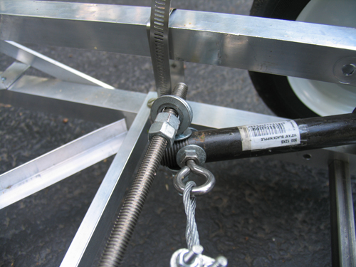
The bain of my existance… the blocks holding the rear sproket are badly made and thus wobble. The axle (1″) has a keyway in it, and the sproken has a 2″ hole. Logically, we’d make spacers to simply hold it in the center, and the spacers would fit the keyway to spin it. I built two of these out of hard wood. I cut the 1″ and keyway with a coping saw (which was a hard process), screwed the whole thing together, and slapped the chain on. It looked perfect. As soon as I touched the throttle, the keyways sheared off (wood doesn’t deal with shear stress very well) and the whole unit simply spun.
Despite efforts to make some sort of key, each time something would slip or shear off as I don't have access to any sort of metal shop. Thus, the steal cable goes through the hole in the sproket and get band clamped to the axle. The wood simply acts to keep the sproket in the right place, and the cable deals with transfering the torque to the axle. It’s ugly, and the chain pops off occasionally. I need to make some sort of mount from aluminum…
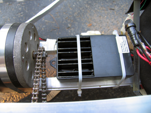
This is basically just a large version of the electronic speed controller in a remote control car. Rather than having huge variable resistors, the “ESC” as its called simply pulses the motor very quickly, and by varying how many of these pulses are “on” and “off” we vary the speed.
Ignition… because I can.
The throttle from the scooter. Yes, it is taped to the side. I haven’t had a chance to fasion some sort of pedal yet.
Three 7 Ah lead acid batteries power this 36v beast… they’re heavy.
Final Thoughts
In case you were wondering, there are no brakes. I haven’t gotten to that yet. But hey, when I get to the transmission and the throttle pedal, perhaps a brake might appear.
I built this “Kart” basically because I wanted to see if I was good at building large (or larger than normal) things, and to satisfy a “project” requirment for my physics class. While most people built small electronics projects on breadboards, I built this. People were pretty surprised.
Update to the update: The frame got turned into a trike for the hang glider, and the motor got imported to a scooter. Both were epic.
Frame
The frame was designed (in my head, since I can’t draw) to be very light, but hopefully still fairly strong. Four 1″ square aluminum stock bars run the length of the frame as 4 edges of a box. Each side of this “box” is then held the proper distance apart by perpendicular flat stock and held rigid by 2 opposite-direction diagnals of either flat stock or square stock.
The cross peices that go between the frame sides in the front are 1/2″ inch steel square stock. It is absolutly key that these side sections stay the same distance apart, as they control the cambre of the wheels. The steel is held in place by threaded rod. (I would have used aluminum, but Home Depot is terrible at restocking and never had enough.)
The front wheels are lame garden wheels from Home Depot (about $8 each) with built in bearings. It remains to be seen how long the bearings will last, but they haven’t fallen out yet…
Steering
The steering idea was conceived by Sean Manix and Joe Gage in a gravity-powered car we built long ago. I modified the design somewhat to work here. Basically, the system works as a rack and pinion system does, minus the rack and the pinion. The tierod keeps outward tension on the steering arms so that they stay the proper distance apart and the wheels stay parallel; the wire pulls the whole sytem to one side or the other to steer while at the same time keeping tension on the steering arms so they stay on the tierod.
Yes, the steering arms are made of plumbing equipment.
Inside those plumbing T’s, bolts come in from both square sections of frame. Roller skate bearings (that I had around and just happened to fit) go over the bolts and space the plumbing to sit in the center. I then put the T’s on the drill press and put the 1/2″ holes in them. Let me tell you, that was scary. The bit has a tendancy to catch coming out the other side, so the whole T arm unit spins around the bit fast enough to break your arm.
As inaccurate as this looks, it actual is very smooth and tight. The steering feels nice while youre driving.
…don’t ask, it’s a school thing somebody wrote. But yes, that is the “steering plank”.
Drive Train
The motor is from an electric scooter. It’s 750 Watts… in pure energy, 1 horsepower = 746 Watts, but I think here the 750w describe amount of power the motor pulls from the batteries, not the mechanical energy put out. Since the motor is likely only moderatly efficient, I’d say it’s in the half-horsepower range.
My girlfriend Erica is building a kart on the same design as this one. I helped her get her motor… hers is 1200w. I think I’ll still be able to beat her once I figure out how to put some sort of transmission on this thing. The chain and rear cog are from the scooter too.
The bain of my existance… the blocks holding the rear sproket are badly made and thus wobble. The axle (1″) has a keyway in it, and the sproken has a 2″ hole. Logically, we’d make spacers to simply hold it in the center, and the spacers would fit the keyway to spin it. I built two of these out of hard wood. I cut the 1″ and keyway with a coping saw (which was a hard process), screwed the whole thing together, and slapped the chain on. It looked perfect. As soon as I touched the throttle, the keyways sheared off (wood doesn’t deal with shear stress very well) and the whole unit simply spun.
Despite efforts to make some sort of key, each time something would slip or shear off as I don't have access to any sort of metal shop. Thus, the steal cable goes through the hole in the sproket and get band clamped to the axle. The wood simply acts to keep the sproket in the right place, and the cable deals with transfering the torque to the axle. It’s ugly, and the chain pops off occasionally. I need to make some sort of mount from aluminum…
This is basically just a large version of the electronic speed controller in a remote control car. Rather than having huge variable resistors, the “ESC” as its called simply pulses the motor very quickly, and by varying how many of these pulses are “on” and “off” we vary the speed.
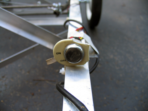
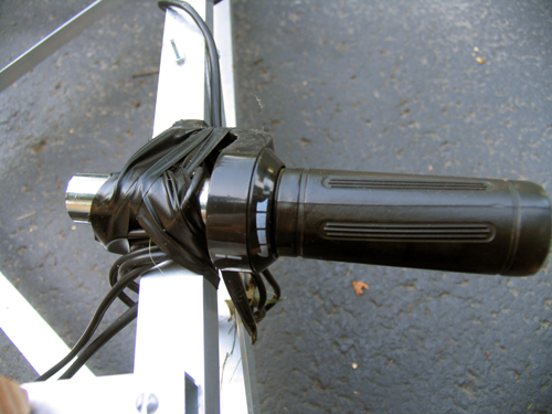
Ignition… because I can.
The throttle from the scooter. Yes, it is taped to the side. I haven’t had a chance to fasion some sort of pedal yet.
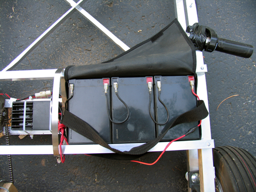
Three 7 Ah lead acid batteries power this 36v beast… they’re heavy.
Final Thoughts
In case you were wondering, there are no brakes. I haven’t gotten to that yet. But hey, when I get to the transmission and the throttle pedal, perhaps a brake might appear.
Email me:
jack {@} crepinc.com
Recent Projects:
Analog HF Transmitter
Audi ECU Reverse Engineering
Dual DAC QAM Modulator
FPGA QAM Modulator
Geiger Counter
Gyro-Stabilized DSLR Platform
Hybrid Rocket Engines
Turbocharger Controller
WWVB Rx and Tx
Older Projects:
Balancing Bot
Capacitor Array
CNC Mill
DCIR Renderer
Electric Gokart
Hovercraft
Low Alt. Temp. Model
Shopping Cart Locker
Trebuchet
My Twitter occasionally shows projects I'm working on.
My GitHub has code from a few projects on it.