Tuesday, February 25. 2014
FPGA Dual DAC Board for QAM Synthesis
Building on the simplicity and success of my DAC board paired with my FPGA dev boards, today I threw together a board with an Altera Cyclone II, two DAC9000Es, an FT245R, and supporting periphery. I'll need to check it with fresh eyes tomorrow to ensure I haven't made any mistakes, but with luck I can submit the design tomorrow evening and have the boards next week.
My DAC+FPGA pair has proved extremely useful for transmitting test signals of various sorts, taking I+Q via USB and generating the output signal in code. But, at 160 MS/s, its max frequency is quite limited. This new board has two of the same DACs, however each will simply generate the I or Q signal alone which will then be combined with an LO in a dedicated QAM modulator chip. This allows for carrier frequencies limited only by the abilities of the QAM modulator chosen, and at 160 MS/s the usable Tx bandwidth will be huge.
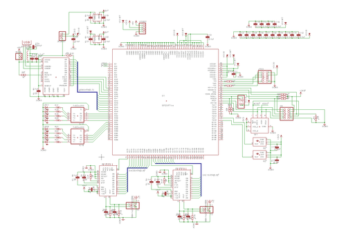
I've chosen to terminate the DACs in SMA connectors and leave the modulator off the board entirely, as I'd like to evaluate a few different chips. Unfortunately this board will be too large for me to mill at home at the moment, but I can still quickly mill test boards for QAM modulators in about an hour.
My DAC+FPGA pair has proved extremely useful for transmitting test signals of various sorts, taking I+Q via USB and generating the output signal in code. But, at 160 MS/s, its max frequency is quite limited. This new board has two of the same DACs, however each will simply generate the I or Q signal alone which will then be combined with an LO in a dedicated QAM modulator chip. This allows for carrier frequencies limited only by the abilities of the QAM modulator chosen, and at 160 MS/s the usable Tx bandwidth will be huge.

I've chosen to terminate the DACs in SMA connectors and leave the modulator off the board entirely, as I'd like to evaluate a few different chips. Unfortunately this board will be too large for me to mill at home at the moment, but I can still quickly mill test boards for QAM modulators in about an hour.
Thursday, February 20. 2014
WWVB Receiver and Testing Transmitter
As I've been making steady progress on my Z80 computer, I've put a lot of thought into something to actually do with it when it's done. As tempting as it is to load up CP/M, add a video interface, and use it as my main machine, I think porting Firefox is too ambitious. For now, I've decided to add some more 7-segment displays and an RF front end to decode the WWVB time signal from an atomic clock in Colorado and hang it on the wall. If I'm still feeling ambitious, I'll add an Ethernet controller and write a driver and NTP daemon for it. Of course, this means I need a working receiver front end for 60kHz.

The WWVB signal is quite simple as far as decoding goes: the carrier has "full power" and "low power" states. The transmitter drops the carrier by 17 dB at the start of each second, and the length of time before it returns provides a single trinary value: Mark (0.8s), Not Set (0.2s), or Set (0.5s). A single digital line that goes low or high to follow the transmitter power state is quite easy to achieve with a fully analog circuit: after a bandpass to select only the 60kHz carrier, we send the signal into two peak detectors - one with a long time constant (low pass filter) to track the average signal power over several seconds, and one with a shorter time constant to track the per-second changes. Passing these two signals to a comparator, we get our nice single-bit TTL indicator of the current signal state. Plus, the longer time constant peak detector acts as an auto gain control, so no alignment is required.
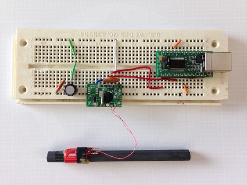
While I will make my own receiver as described above for the final version, I ordered a SYM-RFT module for testing. It includes an LED to indicate received carrier status and outputs the inverted carrier power state compared to the average carrier power. I quickly breadboarded it up to an FT245R USB chip and wrote a few lines of C to poll the power status and measure the length of state changes. Unfortunately, New England being quite far from Colorado, the signal is below the noise floor and has thus far been highly unreliable. The module simply flashes chaotically in the presence of any electronic noise like my monitors, and does nothing in isolation.
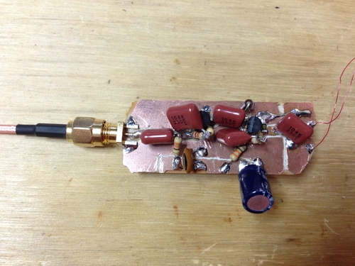
I built the above two-stage preamp from two 2N3904's to attach to the 60kHz antenna that came with the SYM-RFT module to see if I could see any carrier on the oscilloscope. While I did get all sorts of noise and impulses, there was very little if any energy at 60kHz. Drat.
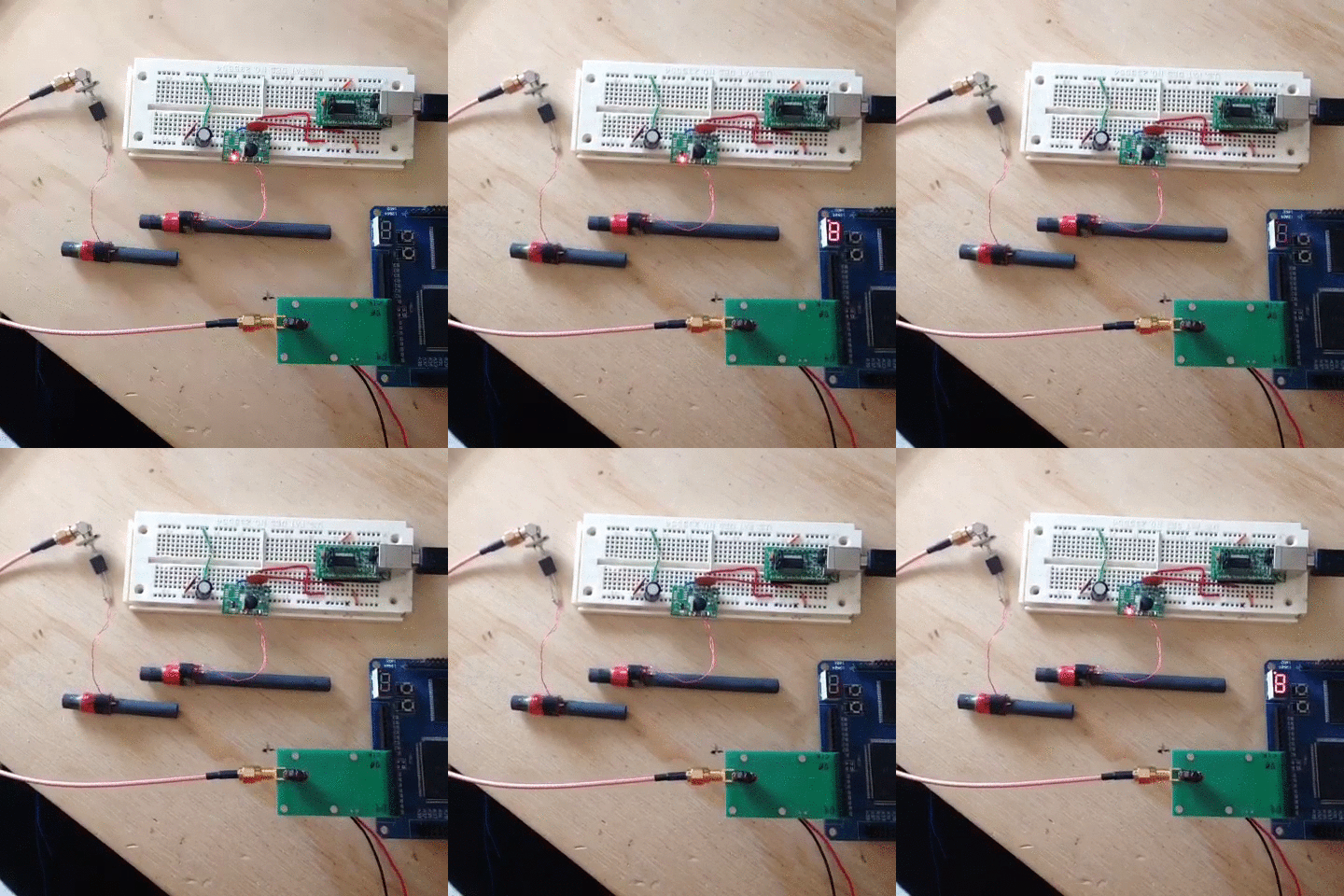
Luckily, I have the tools on hand to recreate the signal so I can at least test my receiver and code. I pulled out the FPGA RF DAC board I put together a while back, and a page of Verilog later I had a compliant WWVB transmitter:
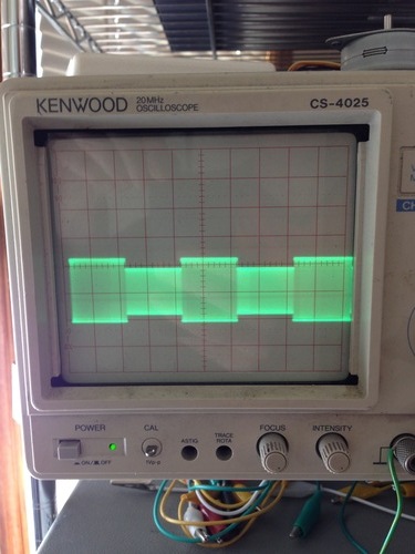
After a small battle with PLLs to get a slow enough clock for 60khz, both the SYM-RFT and my USB worked fine.
jackc@ichor ~/Projects/wwvb_usb $ sudo ./wwvb
MARK : 950 ms
NOT SET : 239 ms
SET : 503 ms
NOT SET : 194 ms
SET : 581 ms
MARK : 991 ms
^Cjackc@ichor ~/Projects/wwvb_usb $
The WWVB signal is quite simple as far as decoding goes: the carrier has "full power" and "low power" states. The transmitter drops the carrier by 17 dB at the start of each second, and the length of time before it returns provides a single trinary value: Mark (0.8s), Not Set (0.2s), or Set (0.5s). A single digital line that goes low or high to follow the transmitter power state is quite easy to achieve with a fully analog circuit: after a bandpass to select only the 60kHz carrier, we send the signal into two peak detectors - one with a long time constant (low pass filter) to track the average signal power over several seconds, and one with a shorter time constant to track the per-second changes. Passing these two signals to a comparator, we get our nice single-bit TTL indicator of the current signal state. Plus, the longer time constant peak detector acts as an auto gain control, so no alignment is required.

While I will make my own receiver as described above for the final version, I ordered a SYM-RFT module for testing. It includes an LED to indicate received carrier status and outputs the inverted carrier power state compared to the average carrier power. I quickly breadboarded it up to an FT245R USB chip and wrote a few lines of C to poll the power status and measure the length of state changes. Unfortunately, New England being quite far from Colorado, the signal is below the noise floor and has thus far been highly unreliable. The module simply flashes chaotically in the presence of any electronic noise like my monitors, and does nothing in isolation.

I built the above two-stage preamp from two 2N3904's to attach to the 60kHz antenna that came with the SYM-RFT module to see if I could see any carrier on the oscilloscope. While I did get all sorts of noise and impulses, there was very little if any energy at 60kHz. Drat.
Luckily, I have the tools on hand to recreate the signal so I can at least test my receiver and code. I pulled out the FPGA RF DAC board I put together a while back, and a page of Verilog later I had a compliant WWVB transmitter:

After a small battle with PLLs to get a slow enough clock for 60khz, both the SYM-RFT and my USB worked fine.

jackc@ichor ~/Projects/wwvb_usb $ sudo ./wwvb
MARK : 950 ms
NOT SET : 239 ms
SET : 503 ms
NOT SET : 194 ms
SET : 581 ms
MARK : 991 ms
^Cjackc@ichor ~/Projects/wwvb_usb $
Monday, November 18. 2013
Vectorplot
Since I don't own a vector analyzer, I've been working on a software implementation for the RTL SDR in flat C (using libusb1) and X11 so I can test my FPGA QAM code. It actually turned out to be much simpler than expected, and is working well thus far.

Right now it plots raw I and Q values on the plane as well as calculated FFT data. Since I haven't implemented clock recovery yet, signals appear as a circle (recall that for a frequency difference of N hz between the incoming signal and the sampling frequency, an N hz rotation around the IQ plane results - thus even a difference of a few hz is too quick to see anything but a circle). That shouldn't be very hard, and at that point it will become fully usable as a vector analyzer.
Code is here: https://github.com/jackcarrozzo/vectorplot.
Tuesday, June 4. 2013
FPGA QAM Generation
I recently drew up a board to connect a fast DAC to FPGA dev boards for the purpose of RF generation. I chose the DAC900E from TI as it's fast (165MS/s), pretty accurate (10-bit), and extremely easy to interface (latches values in on clock edges, doesn't require any setup or external stuff).
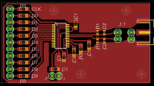
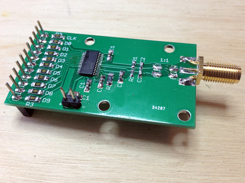
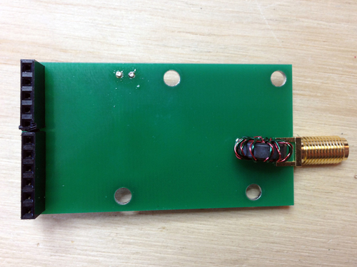
Normally I'd cut a simple one-layer board like this on my CNC mill, but I wanted to try a low cost hobbyist PCB fab I read about via Sparkfun. The did take a very long while, but came out beautifully. Also, when the boards finally arrived, I was pleased I had picked a DAC with so few external requirements to solder. The resistors are there to prevent an output buffer short in case I soldered badly, by the way - I don't own a hot air rework setup.
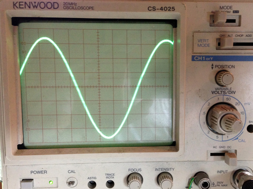
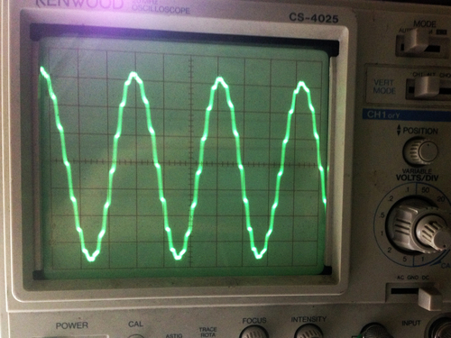
Right off the bat, I was pleased to see that my sine-generation test code worked great at various frequencies and bit depths (aliasing visible in the 2nd pic, its harmonics in the 3rd):
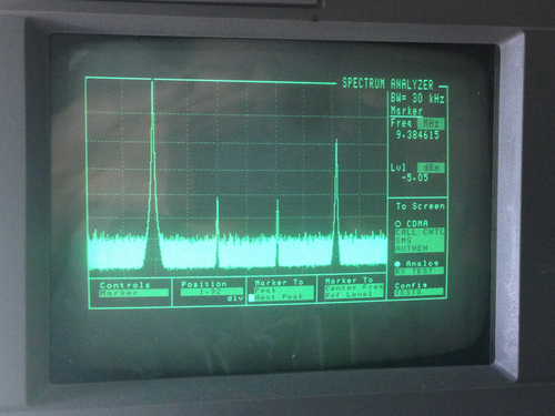
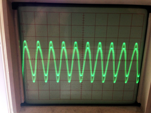
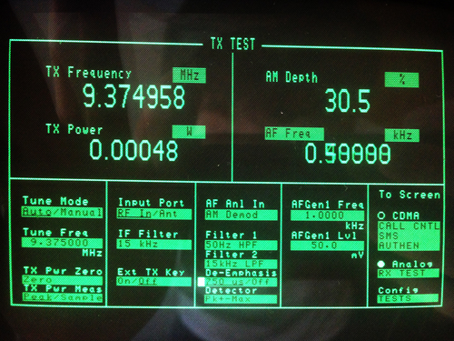
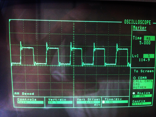
With a bit more hacking, I got the FT245R interface to work such that I send I and Q values via USB, the output value is calculated from an LUT (I originally was doing the math out, but hardware multiply is very slow), and sent to the DAC. In these pics, you can see that I was generating a 500-hz tone over an AM carrier at 9.375 MHz (the 3rd image is the AM-demodulated signal shown on the spectrum analyzer).
My code is on Github here. It's by no means robust or feature-rich, but it does work well in my opinion. When I have time, I'd like to see how far I can take this design. Assuming I don't find any unforseen roadblocks, the next step will be to make a board with two DAC900Es for I and Q generation that feed into a GHz-range QAM modulator that takes its carrier from a PLL on the FPGA, which will theoretically give me full TX control over a wide range of freqs.
Normally I'd cut a simple one-layer board like this on my CNC mill, but I wanted to try a low cost hobbyist PCB fab I read about via Sparkfun. The did take a very long while, but came out beautifully. Also, when the boards finally arrived, I was pleased I had picked a DAC with so few external requirements to solder. The resistors are there to prevent an output buffer short in case I soldered badly, by the way - I don't own a hot air rework setup.
Right off the bat, I was pleased to see that my sine-generation test code worked great at various frequencies and bit depths (aliasing visible in the 2nd pic, its harmonics in the 3rd):
With a bit more hacking, I got the FT245R interface to work such that I send I and Q values via USB, the output value is calculated from an LUT (I originally was doing the math out, but hardware multiply is very slow), and sent to the DAC. In these pics, you can see that I was generating a 500-hz tone over an AM carrier at 9.375 MHz (the 3rd image is the AM-demodulated signal shown on the spectrum analyzer).
My code is on Github here. It's by no means robust or feature-rich, but it does work well in my opinion. When I have time, I'd like to see how far I can take this design. Assuming I don't find any unforseen roadblocks, the next step will be to make a board with two DAC900Es for I and Q generation that feed into a GHz-range QAM modulator that takes its carrier from a PLL on the FPGA, which will theoretically give me full TX control over a wide range of freqs.
Wednesday, February 20. 2013
All-Analog HF Transmitter
I'm going to Puerto Rico soon, and it just so happens we're staying on a beach facing the continental US. Since we won't have internet nor cell service while there, I thought it'd be fun to send tweets via HF as it would be a good excuse to building some simple analog radios. If I use slow synchronous CW driven and detected by FTDI dev boards and a few lines of C, all I need to do is hack up the radios themselves.
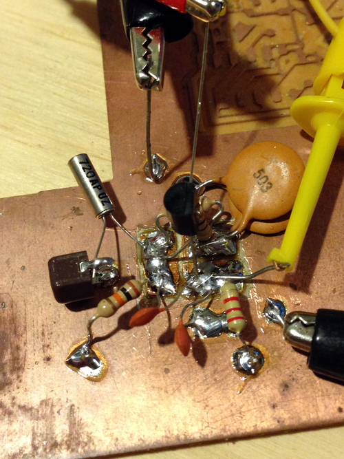
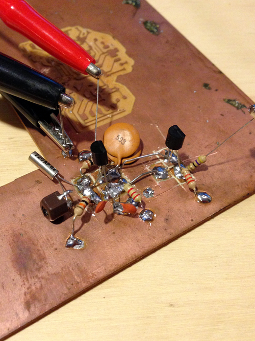
Starting at the TX end, I nabbed a gross piece of PCB from the pile and went to town dead-bugging the transmit chain. Yes, it looks like crap, but if it works as planned I'll design a proper board and cut it on the CNC mill. First I added the crystal oscillator, then its output buffer:
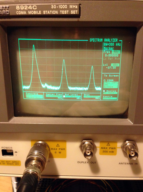
Nice! We can see from the spectrum analyzer that we are indeed getting waves, albeit with some fairly serious harmonics. Now to add a low pass filter:
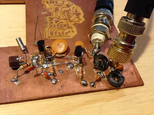

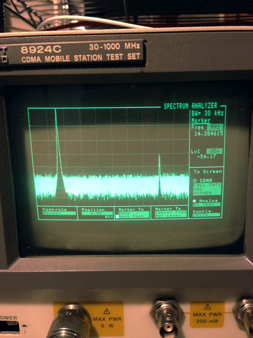
In the first image, you can see that I added connectors between the previous stage's output and the filter's input so I can sweep the filter independently. In the next image, you can see the filter's response on the spectrum analyzer with the tracking generator providing a flat source. Finally, the last image shows our frequency response of the whole system (osc, buffer driver, and filter) - the filter successfully brought the first harmonic down to -54 dBc. Time to add another gain stage and filter:
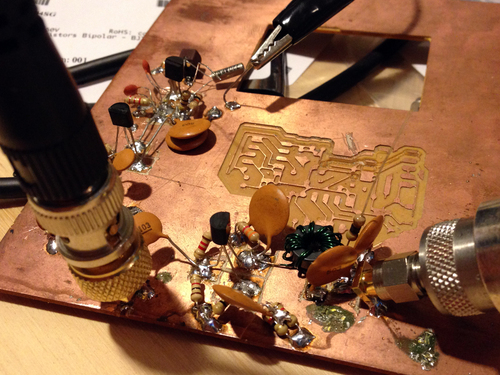
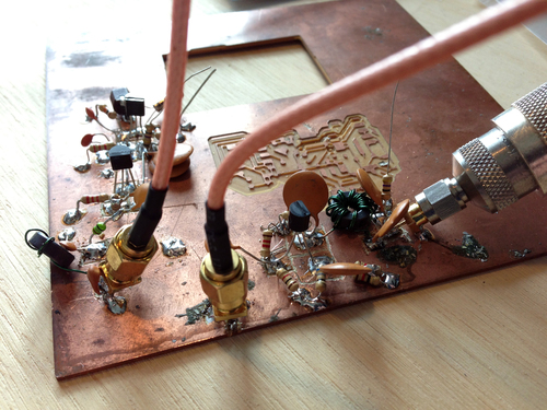
In the first pic, I'm again using the tracking generator to sweep only the response of this amplifier and filter (note that I removed the BNC connector I tacked onto the input of the first filter, and connected it directly to the output of the osc buffer). In the second, the whole chain is hooked up end-to-end. It's putting out 27 dBm (1/2W) at ~7.2 MHz, but the last amplifier transistor get warm quickly - looks like I'm going to need to replace that with something beefier.
Update: Unfortunately I got wicked busy with work prior to leaving for PR and wasn't able to finish this. I do hope to pick it up again soon...
Starting at the TX end, I nabbed a gross piece of PCB from the pile and went to town dead-bugging the transmit chain. Yes, it looks like crap, but if it works as planned I'll design a proper board and cut it on the CNC mill. First I added the crystal oscillator, then its output buffer:
Nice! We can see from the spectrum analyzer that we are indeed getting waves, albeit with some fairly serious harmonics. Now to add a low pass filter:
In the first image, you can see that I added connectors between the previous stage's output and the filter's input so I can sweep the filter independently. In the next image, you can see the filter's response on the spectrum analyzer with the tracking generator providing a flat source. Finally, the last image shows our frequency response of the whole system (osc, buffer driver, and filter) - the filter successfully brought the first harmonic down to -54 dBc. Time to add another gain stage and filter:
In the first pic, I'm again using the tracking generator to sweep only the response of this amplifier and filter (note that I removed the BNC connector I tacked onto the input of the first filter, and connected it directly to the output of the osc buffer). In the second, the whole chain is hooked up end-to-end. It's putting out 27 dBm (1/2W) at ~7.2 MHz, but the last amplifier transistor get warm quickly - looks like I'm going to need to replace that with something beefier.
Update: Unfortunately I got wicked busy with work prior to leaving for PR and wasn't able to finish this. I do hope to pick it up again soon...
Sunday, January 6. 2013
Dual DAC I+Q Generation and Carrier Modulation
I wanted a simple, easily-interfacable QAM source to test some code I had written for the RTL-SDR, so I put together two small boards: one with two SPI DACs to generate the I and Q inputs, and one board with a single analog QAM modulator on it that takes the carrier, I, and Q signals and outputs the modulated carrier.
First, I made the dual DAC board with two MAX515's - simple, 10-bit, SPI DACs.
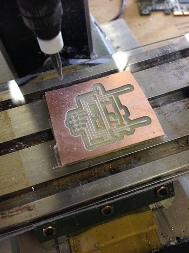
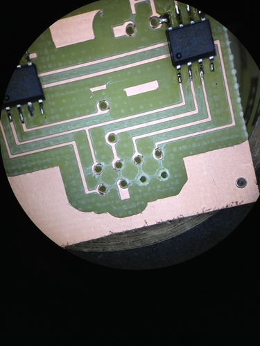
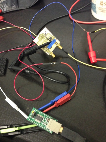
Aesthetically the board was not stunning - I used too large a drill for the through holes, and thus my pads were blown out. However, it was salavgable, so I continued putting it together and testing it by bit-banging the DACs with an FT245R dev board:
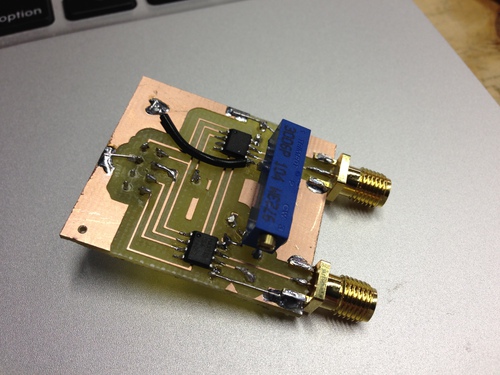
With that working well, I dead-bugged the modulator, a TRF370417 that will handle carrier freqs of 50 MHz through 6 GHz, to another board:
As pretty as that board turned out, it was unfortunately (and predictably) extremely noisy. Oh well, I suppose I will just have to make a proper board for all 3 chips...
First, I made the dual DAC board with two MAX515's - simple, 10-bit, SPI DACs.
Aesthetically the board was not stunning - I used too large a drill for the through holes, and thus my pads were blown out. However, it was salavgable, so I continued putting it together and testing it by bit-banging the DACs with an FT245R dev board:
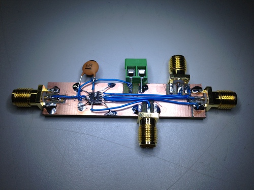
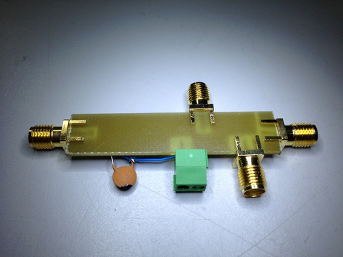
With that working well, I dead-bugged the modulator, a TRF370417 that will handle carrier freqs of 50 MHz through 6 GHz, to another board:
As pretty as that board turned out, it was unfortunately (and predictably) extremely noisy. Oh well, I suppose I will just have to make a proper board for all 3 chips...
Wednesday, October 24. 2012
FSK Demod and Clock Recovery
I've been working on coding some FSK demodulation and clock recovery in C, since GNUradio's documentation is terrible. My target bitstream is the control channel on the local Motorola Smartzone IIi system, which is 3600 baud. Ideally the code, when finished, will log calls and group associations to make pretty graphs (the system I have doing this currently is a terribly ghetto mess of Windows programs from 1998 and perl.)
The first thing I did was record samples of the stream in two ways: from the soundcard connected to the discriminator tap of my scanner, and from my RTL-SDR dongle. I normalized both outputs into unsigned chars (uint8_t) for simplicity, then coded a quick histogram to make sure my two FSK levels were easily visible. It turns out they are!
8: ######
16: ########################
24: #######################################################
32: ###########################################################################################
40: ###################################################################################################
48: ########################################
56: #############
64: ###########
72: ##########
80: #########
88: #########
96: ########
104: ########
112: ########
120: ########
128: #######
136: ########
144: ########
152: ########
160: ########
168: ########
176: #########
184: ##########
192: ###########
200: ###############
208: #############################
216: ###########################################################
224: #################################################################################
232: ###############################################################
240: #################################
248: ############
The labels on the left are the base value of the bin being graphed, ie "192" is the sum of all samples from 192 to 199, inclusive. As you can see, there are lots of samples at both ends of the plot and very few in the center, which shows that our signal is clean.
After I had confirmed that my samples were in fact sensible, I gave some thought to clock recovery. Since both my streams were recorded at 44.1khz in order to be soundcard-compatible, there are just over 12 samples per symbol. However, since the number isn't exactly 12 as well as local oscillator differences, one can't simply determine the center of one symbol then extrapolate ad infinium from there.
There are entire books written on clock recovery schemes, but suffice to say this problem is generally solved by a PLL that gets 'nudged' forward or backwards in time based on the rate of change of the signal when the symbol is sampled. However, it's generally advantageous to try the simplest solution first.
I hacked up a quick sliding window sampling function that simply tries all 12 available offsets on the given "chunk" of samples (about 1/10th of a second worth), and determines which offset gives the lowest mean signal error. When the chunksize is small enough that the clock error during that period is less than one symbol wide, all the bits are successfully recovered. The process repeats at the next chunk, and no one is the wiser. Clearly this method isn't fast, but I was able to write and test it in an hour.
I was able to dump the binary stream from the samples recorded, however it turns out the data is interleaved and I can't find a spec document (Smartzone is a closed standard.) Unfortunately, until I figure that out, I'm stuck.
Wednesday, September 5. 2012
Embedded WiFi with an RN-XV
I picked up an RN-XV from Sparkfun to see what it would do. I didn't read the docs before I ordered, and I expected to be reading and writing registers and building my own packets. However, I was almost disappointed to learn how much functionality is supported within and how easy it is to get working.
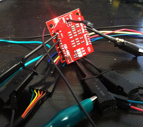
The RN-XV is a carrier board for Roving Networks' RN-171 WiFi module. Since the XV is meant to be pin compatible with the Xbees which use an odd pin spacing, I also ordered an Xbee Explorer Regulated to make connections and power easy (the FTDI cables I have are logic 3.3v but 5v Vcc, so the regulator is needed).
I plugged TX to Din, RX to Dout, added power, and BAM! Blinky lights!
WiFly Ver 2.32, 02-13-2012 on RN-171
MAC Addr=00:06:66:72:20:58
Auto-Assoc roving1 chan=0 mode=NONE FAILED
Unfortunately, it didn't respond to my serial input. After a bunch of tracing and reading, it turns out that the Xbee board does logic level shifting with diodes. The Xbees's have pullup resistors in their Din pins, however the RN modules do not. After adding a 10k resistor from Vcc to Din, I was able to link it to my network and ping things first try.
CMD
<2.32> set wlan phrase myWifiPasswd
AOK
<2.32> join mySSID
Auto-Assoc secure chan=11 mode=WPA1 SCAN OK
Joining mySSID now..
<2.32> Associated!
DHCP: Start
DHCP in 775ms, lease=86400s
IF=UP
DHCP=ON
IP=192.168.9.61:2000
NM=255.255.255.0
GW=192.168.9.1
Listen on 2000
ping 4.2.2.1
Ping try 4.2.2.1
<2.32> 64 bytes from 4.2.2.1: seq=1 ttl=251 time=6.56 ms
64 bytes from 4.2.2.1: seq=2 ttl=251 time=6.41 ms
<2.32>
With the default settings, you can open a socket to the device via wifi on port 2000. Any data that arrives goes out the serial, and any data in the serial goes out the socket. Easy as pie. Now I just need to find something cool to do with it...
For the curious: RN-XV Datasheet (pinout), RN-171 Manual and Command Set
The RN-XV is a carrier board for Roving Networks' RN-171 WiFi module. Since the XV is meant to be pin compatible with the Xbees which use an odd pin spacing, I also ordered an Xbee Explorer Regulated to make connections and power easy (the FTDI cables I have are logic 3.3v but 5v Vcc, so the regulator is needed).
I plugged TX to Din, RX to Dout, added power, and BAM! Blinky lights!
WiFly Ver 2.32, 02-13-2012 on RN-171
MAC Addr=00:06:66:72:20:58
Auto-Assoc roving1 chan=0 mode=NONE FAILED
Unfortunately, it didn't respond to my serial input. After a bunch of tracing and reading, it turns out that the Xbee board does logic level shifting with diodes. The Xbees's have pullup resistors in their Din pins, however the RN modules do not. After adding a 10k resistor from Vcc to Din, I was able to link it to my network and ping things first try.

CMD
<2.32> set wlan phrase myWifiPasswd
AOK
<2.32> join mySSID
Auto-Assoc secure chan=11 mode=WPA1 SCAN OK
Joining mySSID now..
<2.32> Associated!
DHCP: Start
DHCP in 775ms, lease=86400s
IF=UP
DHCP=ON
IP=192.168.9.61:2000
NM=255.255.255.0
GW=192.168.9.1
Listen on 2000
ping 4.2.2.1
Ping try 4.2.2.1
<2.32> 64 bytes from 4.2.2.1: seq=1 ttl=251 time=6.56 ms
64 bytes from 4.2.2.1: seq=2 ttl=251 time=6.41 ms
<2.32>
With the default settings, you can open a socket to the device via wifi on port 2000. Any data that arrives goes out the serial, and any data in the serial goes out the socket. Easy as pie. Now I just need to find something cool to do with it...
For the curious: RN-XV Datasheet (pinout), RN-171 Manual and Command Set
Sunday, February 17. 2008
Radios Radios Everywhere
I got my pretty new radio a few days ago. My Motorola XTS 2500 is quite nice, I have to say. It’s the second to most epic handheld Motorola makes. In addition to the things my HT1250 does like MDC signalling and whatnot, the XTS series supports APCO Project 25. This standard, P25 for short, is a digital protocol for signalling and voice over radio. It’s mostly used in the public safety bands, since digital works better than analog covereage (in general: if the packets can be pulled out of the noise at all, the original audio is maintainted). Kurt, N1PFC came by and helped me program the radio for all my various Ham things in the area (I didn’t own a VHF handheld before so this list is pretty extensive) as well as his P25 Ham repeater not far away.
In other news, I finally got around to doing my Extra class ham license. I got a new call sign while I was at it, and as such I am now NA1C.
In other news, I finally got around to doing my Extra class ham license. I got a new call sign while I was at it, and as such I am now NA1C.
Thursday, January 24. 2008
Talking to Space
In an effort to promote radio and space to other WPI students and staff, Theo, KC2RMJ and I (KB1OZL, now NA1C) put together an event with WPI Wireless to talk to the International Space Station during a particularly good pass last November. I found the pictures of the event and thought they were nice.

I put together one of our (WPIWA’s) smaller towers for the event, and kept it outside my apartment for a few days leading up to the event. Also, I built a 2 meter J Pole antenna since it had pretty good gain at the horizon to help lengthen our window. I modified it a bit from what hams generally use (I used much larger tubing), but as I expected it made the antenna much more wideband. We got about 6 dBi, at <1.5 SWR across the band. Nice!
Unfortunatly, the ISS was speaking packet that day, and we were expecting voice. It was certainly fun to hear a space station transmitting, but it still would have been nicer to get voice.
Tuesday, November 28. 2006
H4x0ring Price Chopper
Forewarning: I may or may not have participated in any of the events listed herein. This may be pure fiction, take from it what you will. That said, it was pretty awsome…
If you’ve ever been to a supermarket in a city (like Worcester), you’ll have likely noticed a locking mechanism on one of the front wheels. It’s designed to lock the cart so that it won’t roll when you try to take it off the lot, so that people don’t steal them.
Around the perimeter of the parking lot, there is a wire acting as an antenna, transmitting an 8 khz square wave gated at 30 ms. This is the locking function. Using two LM555 timers, a few capacitors and resistors, and a coil of wire, a friend and I made our own transmitter.
The transmitter was in my pocket with two switches: to select between lock and unlock, and to active the coil. Since the coil was down at my ancle, this waranted a wire up my pants.
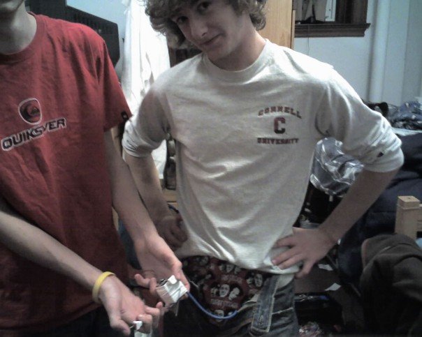
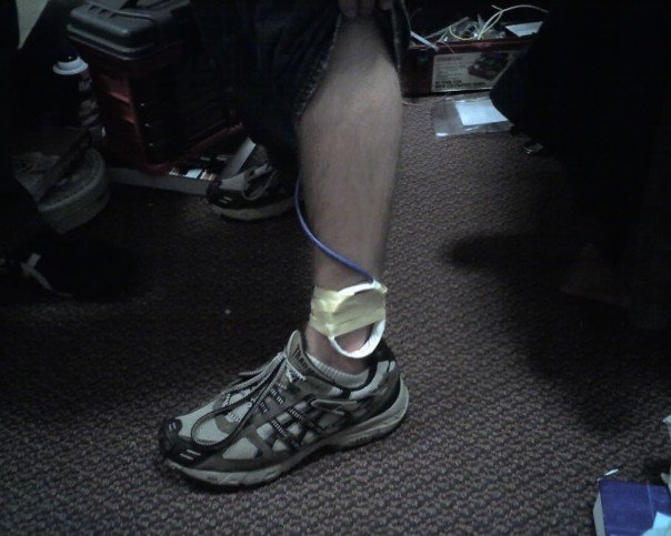
We headed down to the supermarket in the middle of the night, and walked past a line of carts outside: click click click click click click click. They were all locked. The transmitter worked the first time.
We went inside and locked a few carts while they were moving as well, which obivously confused the people moving them.
If you’ve ever been to a supermarket in a city, you’ll have likely seen a lock on one of the front wheels of the carts to prevent people from stealing them. A friend and I managed to make a transmitter so that we could the carts would lock when I walked by with the transmitter in my pants.
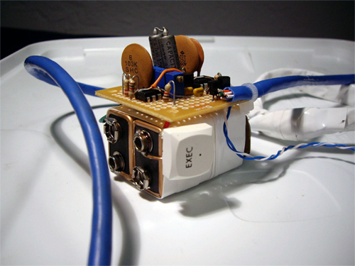
If you’ve ever been to a supermarket in a city (like Worcester), you’ll have likely noticed a locking mechanism on one of the front wheels. It’s designed to lock the cart so that it won’t roll when you try to take it off the lot, so that people don’t steal them.
Around the perimeter of the parking lot, there is a wire acting as an antenna, transmitting an 8 khz square wave gated at 30 ms. This is the locking function. Using two LM555 timers, a few capacitors and resistors, and a coil of wire, a friend and I made our own transmitter.
The transmitter was in my pocket with two switches: to select between lock and unlock, and to active the coil. Since the coil was down at my ancle, this waranted a wire up my pants.


We headed down to the supermarket in the middle of the night, and walked past a line of carts outside: click click click click click click click. They were all locked. The transmitter worked the first time.
We went inside and locked a few carts while they were moving as well, which obivously confused the people moving them.
If you’ve ever been to a supermarket in a city, you’ll have likely seen a lock on one of the front wheels of the carts to prevent people from stealing them. A friend and I managed to make a transmitter so that we could the carts would lock when I walked by with the transmitter in my pants.
(Page 1 of 1, totaling 11 entries)
Email me:
jack {@} crepinc.com
Recent Projects:
Analog HF Transmitter
Audi ECU Reverse Engineering
Dual DAC QAM Modulator
FPGA QAM Modulator
Geiger Counter
Gyro-Stabilized DSLR Platform
Hybrid Rocket Engines
Turbocharger Controller
WWVB Rx and Tx
Older Projects:
Balancing Bot
Capacitor Array
CNC Mill
DCIR Renderer
Electric Gokart
Hovercraft
Low Alt. Temp. Model
Shopping Cart Locker
Trebuchet
My Twitter occasionally shows projects I'm working on.
My GitHub has code from a few projects on it.