Wednesday, May 14. 2014
Interfacing Cirrus Logic Audio ADCs
I've been considering ideas for audio gear of various sorts over the past few months, and decided a good starting place would be a solid ADC interface from which I could prototype concepts. Lots of companies make audio converters, but I settled on two models from Cirrus Logic: the CS5361 and CS5340. They are, respectively, balanced and unbalanced two-channel 24-bit 192 khz high dynamic range delta-sigma oversampling devices.
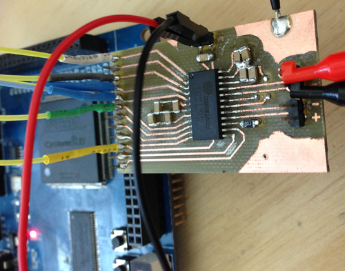
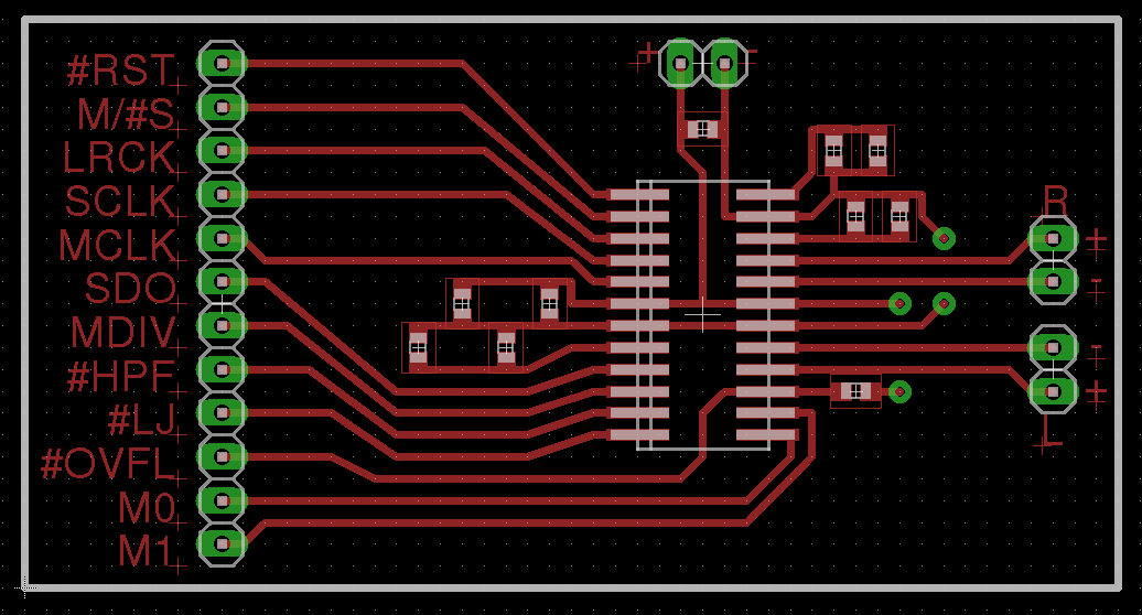
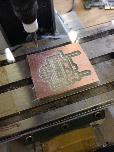
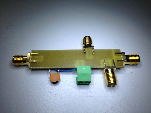
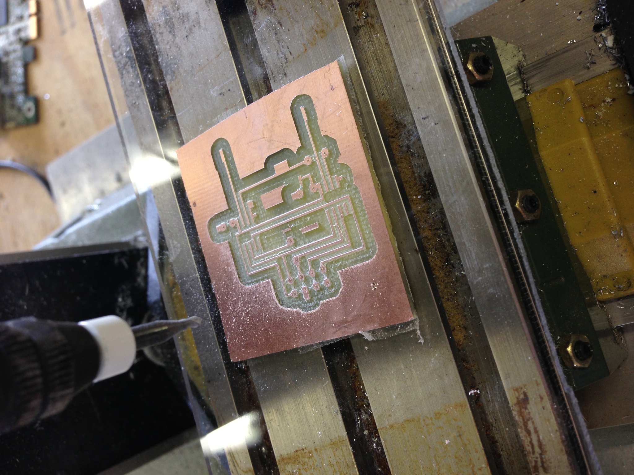
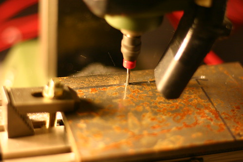
I started by laying out a super-simple protoboard for the CS5361. Since I wanted this to be quick and easy to cut on the CNC mill, the board is single-sided with the bare minimum of filtering, and without standard mixed signal board design concepts like separate analog and digital ground planes. While this will negatively affect the noise figure a bit, I wanted to get the device up and running with the minimum investment of time in case my assumptions regarding its usage and support were incorrect.

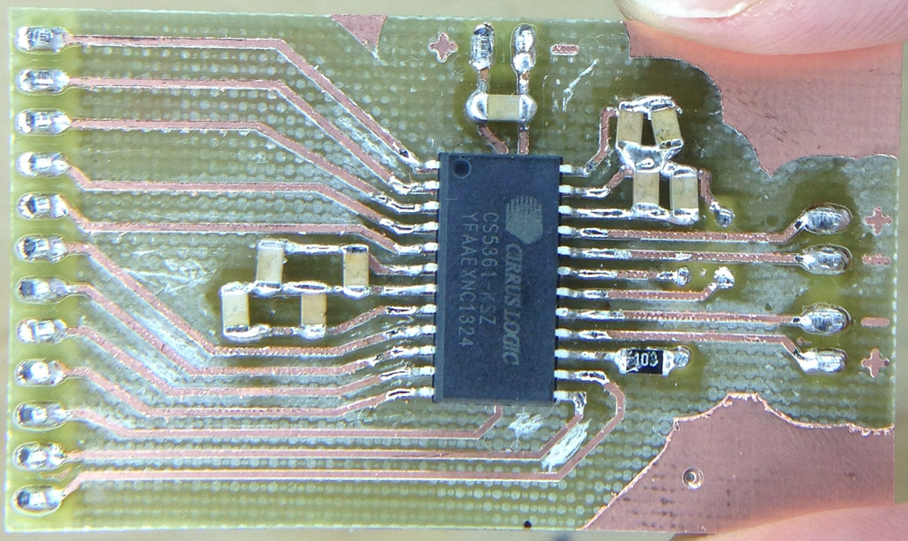
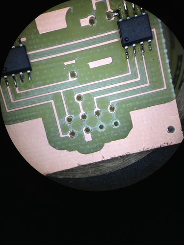
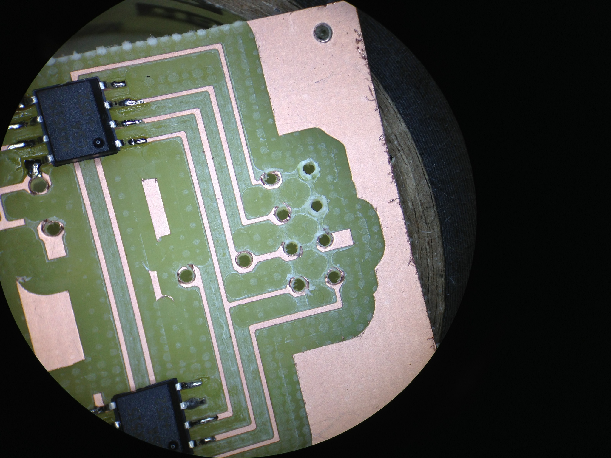
By the time I had finished the layout and cut the board, the samples order had arrived! Soldering was quick though a tad arduous - I need to use a larger 1206 footprint next time.

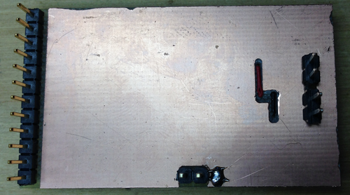
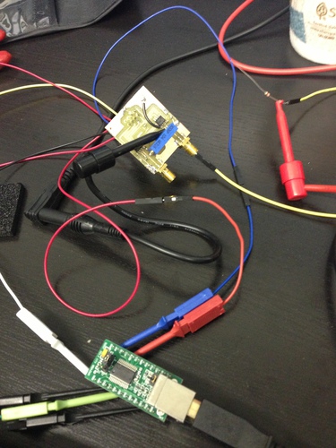
My ugly solder job notwithstanding, I plugged the unit into a breadboard, wired up an oscillator, config pins, and the logic analyzer, and was immediately rewarded with correct operation:
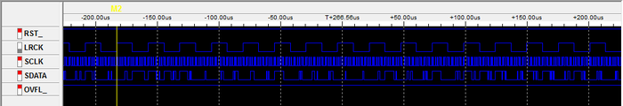
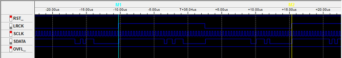
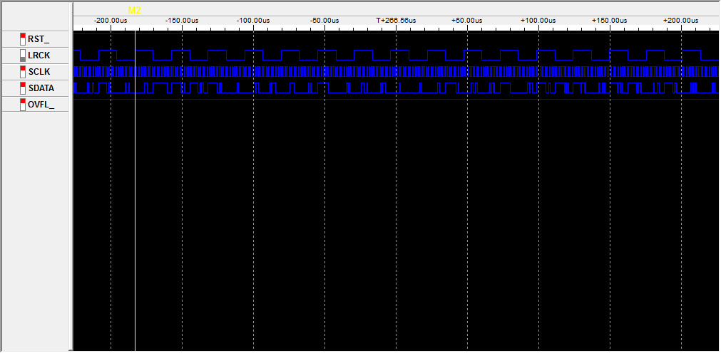
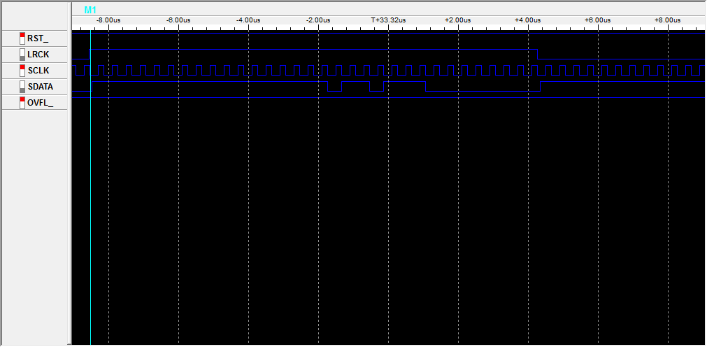
In short, by simply applying power, config pin states, and a master clock, the device will shift out ADC values (in 2's compliment form) msb-first on the falling edge of SCLK (ie, we sample on the rising edge):

The only other line we need to worry about is LRCK, which indicates the channel being sent - you can see here that we get a left sample, then a right sample, then repeat:
With the hardware working, I set about writing the Verilog modules to nab samples from the ADC and send them off via USB (using an FT245R FIFO interface I have on hand). The code is extremely simple: on the rising edge of SCLK, samples are shifted into an 8-bit register - the size of the data bus on the USB interface. Every 8 bits, that register is strobed into the FT245R and the process repeats.
Byte alignment is provided by LRCK: on a start or reset condition from the USB host, the FPGA waits for a rising edge of LRCK before beginning the sampling and transmission of samples. This allows the client end to interpret the data stream without framing bytes: incoming data is simply shifted into 3-byte (24-bit) samples, left then right, and processed as desired.
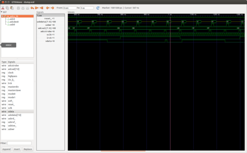
The code was quick to write and simulate with my favorite tools, iVerilog and GTKWave. I implemented a quick CS5361 module whose left and right channels count up and down (respectively) so as to simulate the rest of the pieces. Unfortunately I spent almost as much time debugging the code in hardware with the logic analyzer as I did writing the code, as Quartus (the Altera design software) is rather inconsistent in its handling of constants and register widths. (note: always read every line of output from the Altera synthesis toolchain - one can easily spend 4 hours trying to debug a problem that makes no sense only to find that the synthesis tool decided a constant was the wrong size and used zero instead)
In any event, I did manage to squash the few Quartus oddities that had caused the hardware to operate differently from the simulated code, and verified that the USB interface looked correct using the logic analyzer. Time for more spaghetti:
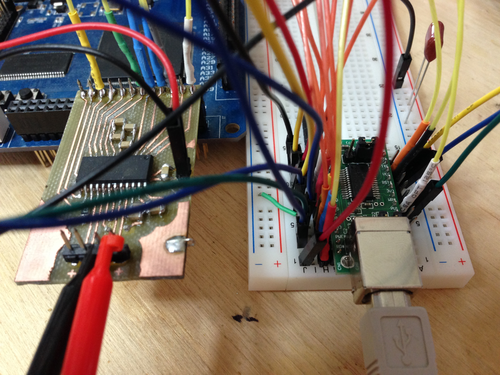
Time to test it out. In its current state, the FPGA will assert a reset condition on any received byte from the FIFO buffer. So, we will send a reset byte then read 24 samples of 6 bytes (3 for each channel):
root@ichor ~ # echo -n 0 > /dev/ttyUSB0 && dd if=/dev/ttyUSB0 count=24 bs=6 2>/dev/null | hexdump
0000000 3238 a13f 4a68 a650 0344 bd41 6632 ceaa
0000010 78f2 28f8 9764 19ca 7185 45b4 6bfd eabf
0000020 9825 8050 65e5 6122 3adc 0830 28f0 9dfc
0000030 d026 746a e2c0 befa 57dc 1fa4 4225 7b82
0000040 a61b ed00 2320 d641 e111 b648 a2f3 8d3a
0000050 bdfb afb6 1287 5963 ff57 9c8e 63a1 3971
0000060 4bfe ac6e 5081 9fae 2b0d 5c4c 6eaa 26b7
0000070 164b 6093 8378 96d8 138c 160e e661 a81b
0000080 81bc bdae 530b ec79 3537 6ada b0cc 4773
0000090
Success! With that working, the next steps are to implement the CS5340 and add proper dynamic configuration loading. From there, I am hoping to implement ADAT input and output and a simple device driver to interface the kernel audio subsystem.
I've put the code, board design, and a bit of documentation on GitHub: jackcarrozzo/cs_adcs.
I started by laying out a super-simple protoboard for the CS5361. Since I wanted this to be quick and easy to cut on the CNC mill, the board is single-sided with the bare minimum of filtering, and without standard mixed signal board design concepts like separate analog and digital ground planes. While this will negatively affect the noise figure a bit, I wanted to get the device up and running with the minimum investment of time in case my assumptions regarding its usage and support were incorrect.
By the time I had finished the layout and cut the board, the samples order had arrived! Soldering was quick though a tad arduous - I need to use a larger 1206 footprint next time.

My ugly solder job notwithstanding, I plugged the unit into a breadboard, wired up an oscillator, config pins, and the logic analyzer, and was immediately rewarded with correct operation:
In short, by simply applying power, config pin states, and a master clock, the device will shift out ADC values (in 2's compliment form) msb-first on the falling edge of SCLK (ie, we sample on the rising edge):
The only other line we need to worry about is LRCK, which indicates the channel being sent - you can see here that we get a left sample, then a right sample, then repeat:

With the hardware working, I set about writing the Verilog modules to nab samples from the ADC and send them off via USB (using an FT245R FIFO interface I have on hand). The code is extremely simple: on the rising edge of SCLK, samples are shifted into an 8-bit register - the size of the data bus on the USB interface. Every 8 bits, that register is strobed into the FT245R and the process repeats.
Byte alignment is provided by LRCK: on a start or reset condition from the USB host, the FPGA waits for a rising edge of LRCK before beginning the sampling and transmission of samples. This allows the client end to interpret the data stream without framing bytes: incoming data is simply shifted into 3-byte (24-bit) samples, left then right, and processed as desired.

The code was quick to write and simulate with my favorite tools, iVerilog and GTKWave. I implemented a quick CS5361 module whose left and right channels count up and down (respectively) so as to simulate the rest of the pieces. Unfortunately I spent almost as much time debugging the code in hardware with the logic analyzer as I did writing the code, as Quartus (the Altera design software) is rather inconsistent in its handling of constants and register widths. (note: always read every line of output from the Altera synthesis toolchain - one can easily spend 4 hours trying to debug a problem that makes no sense only to find that the synthesis tool decided a constant was the wrong size and used zero instead)

In any event, I did manage to squash the few Quartus oddities that had caused the hardware to operate differently from the simulated code, and verified that the USB interface looked correct using the logic analyzer. Time for more spaghetti:

Time to test it out. In its current state, the FPGA will assert a reset condition on any received byte from the FIFO buffer. So, we will send a reset byte then read 24 samples of 6 bytes (3 for each channel):
root@ichor ~ # echo -n 0 > /dev/ttyUSB0 && dd if=/dev/ttyUSB0 count=24 bs=6 2>/dev/null | hexdump
0000000 3238 a13f 4a68 a650 0344 bd41 6632 ceaa
0000010 78f2 28f8 9764 19ca 7185 45b4 6bfd eabf
0000020 9825 8050 65e5 6122 3adc 0830 28f0 9dfc
0000030 d026 746a e2c0 befa 57dc 1fa4 4225 7b82
0000040 a61b ed00 2320 d641 e111 b648 a2f3 8d3a
0000050 bdfb afb6 1287 5963 ff57 9c8e 63a1 3971
0000060 4bfe ac6e 5081 9fae 2b0d 5c4c 6eaa 26b7
0000070 164b 6093 8378 96d8 138c 160e e661 a81b
0000080 81bc bdae 530b ec79 3537 6ada b0cc 4773
0000090
Success! With that working, the next steps are to implement the CS5340 and add proper dynamic configuration loading. From there, I am hoping to implement ADAT input and output and a simple device driver to interface the kernel audio subsystem.
I've put the code, board design, and a bit of documentation on GitHub: jackcarrozzo/cs_adcs.
Wednesday, February 13. 2013
Exhaust Turbine Attempt
A few years ago, I built a gas turbine engine from an old car turbocharger with my friends Chris and Ken. Chris happens to work for a jet manufacturer for a living, so he knows a great deal about such topics. Chris and I have been plotting for some time to design a very simple two-stage axial flow single combustor engine, and the biggest thing holding us back is the ability to actually create the parts we design.
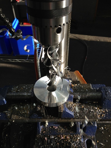
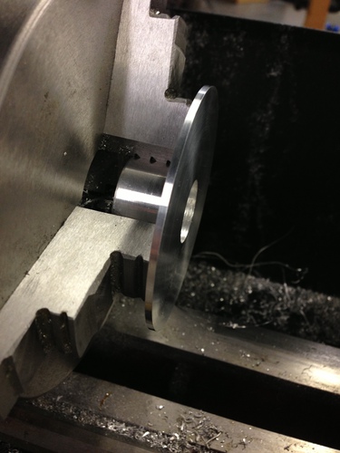
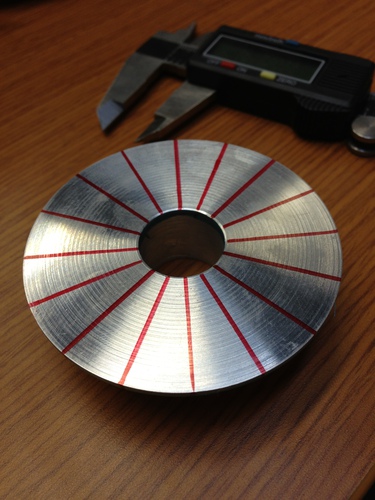
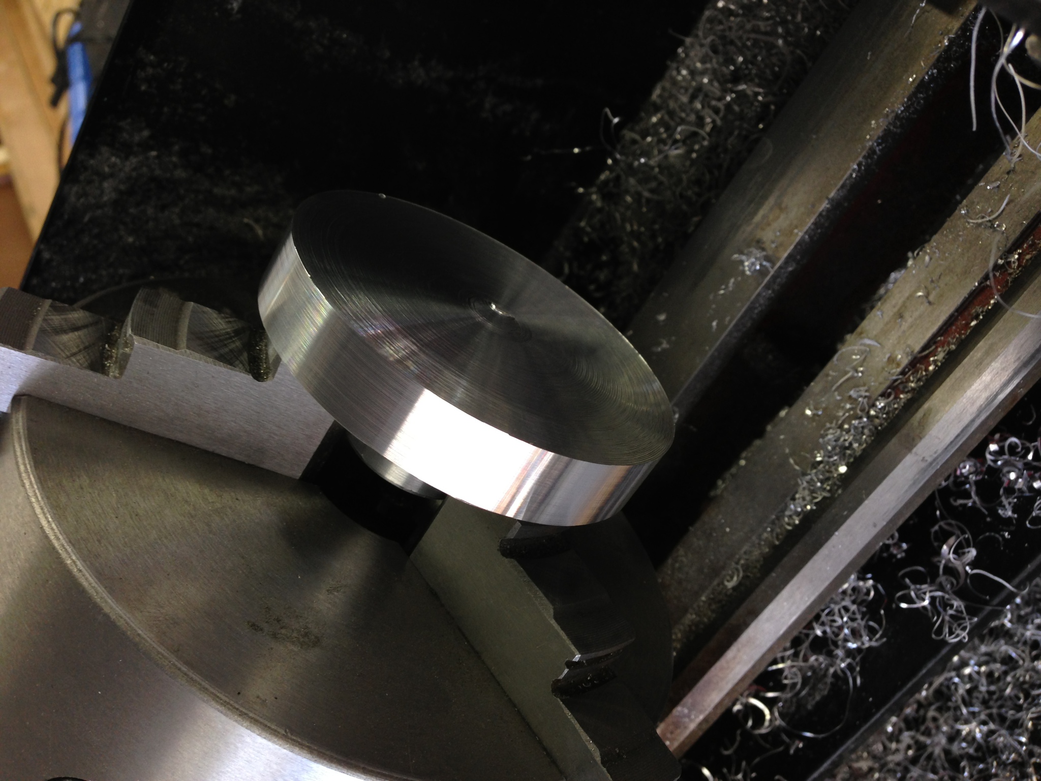
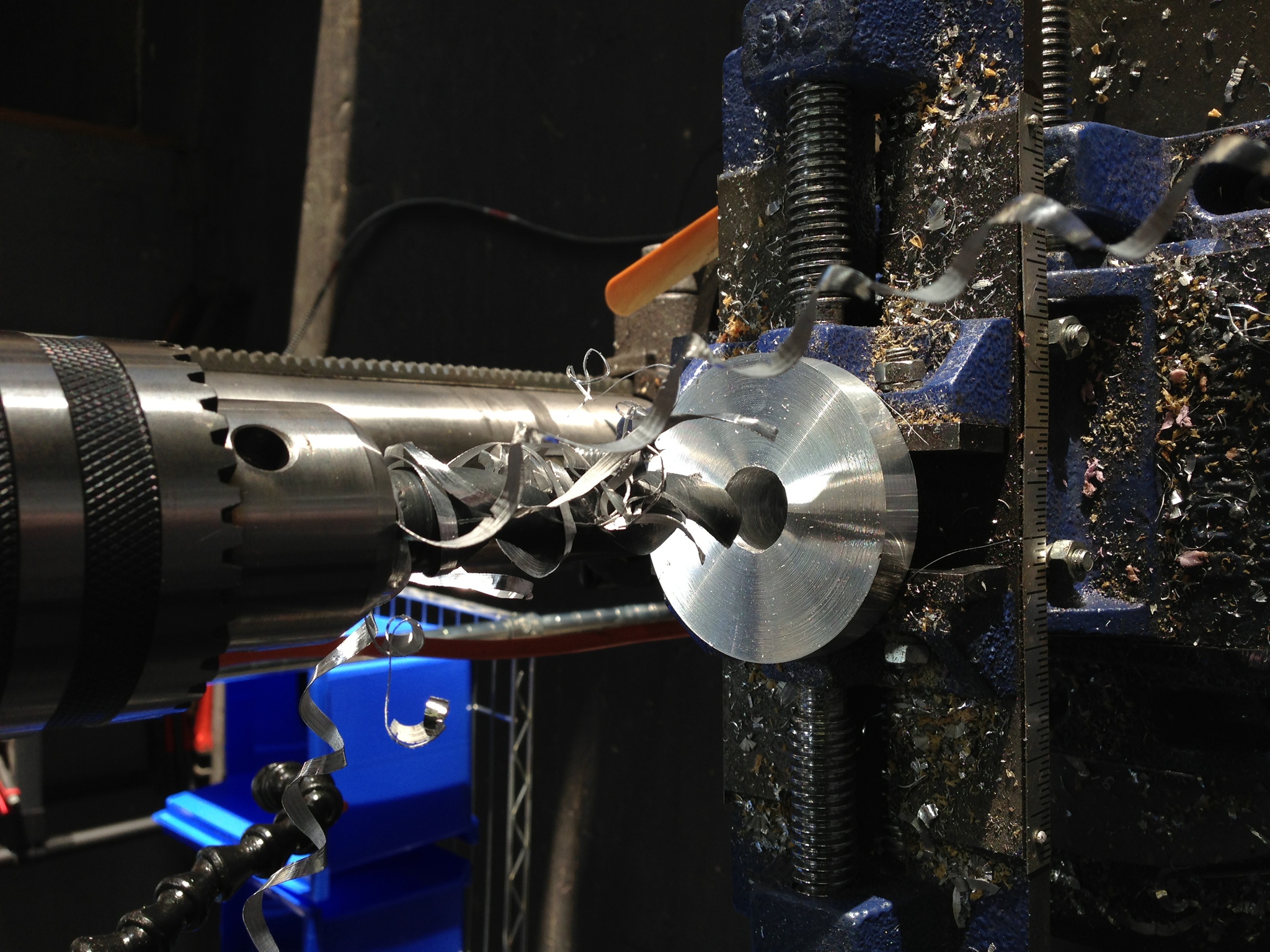
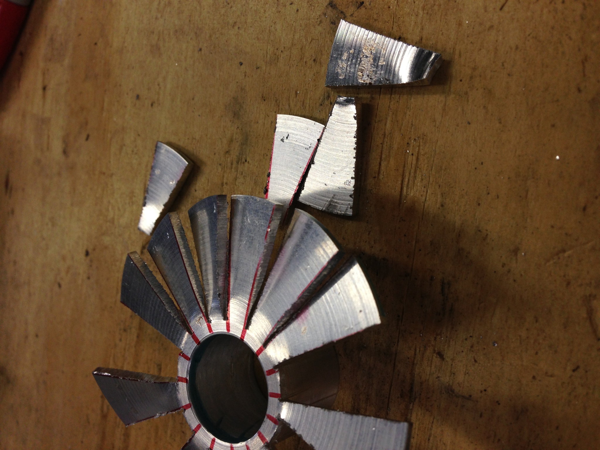
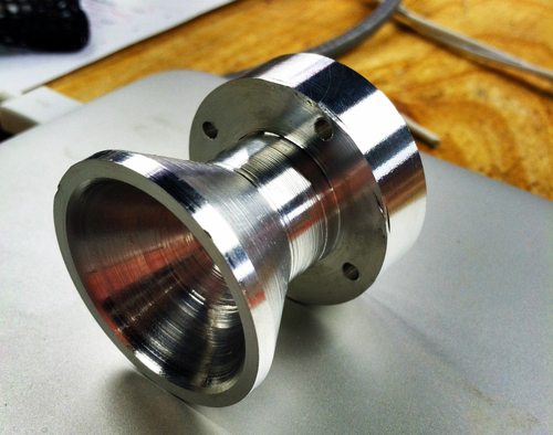
I spent some time playing with Aluminium (6061-T6) on my lathe to see if I could make a simple exhaust turbine wheel by separating a disk into fins and twisting them then sanding the edges into a semi-airfoil shape. First I roughed out the general shape I was going for, and drilled the hole through the center (my lathe bed isn't long enough to do so).
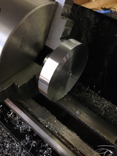
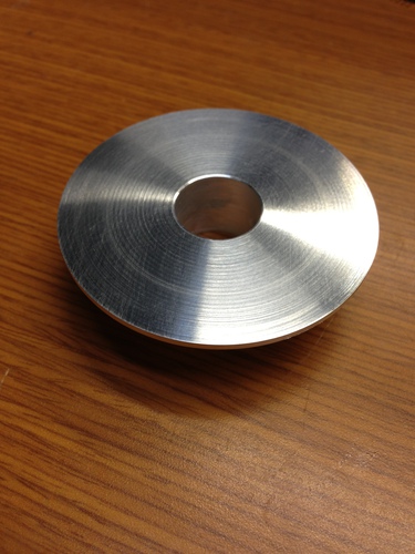
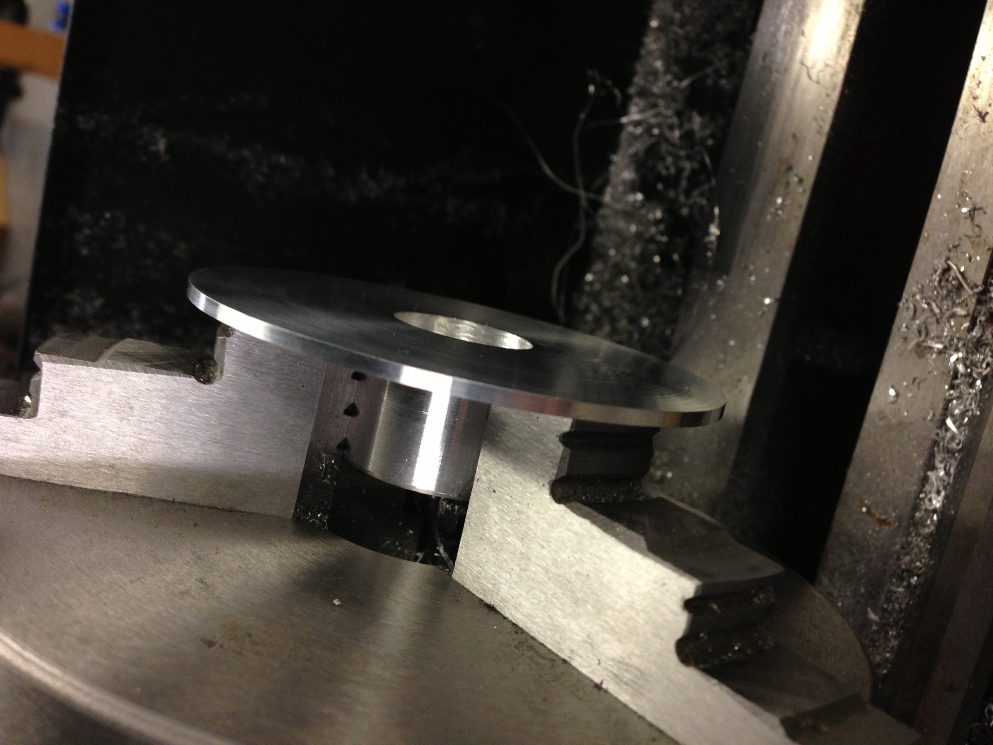
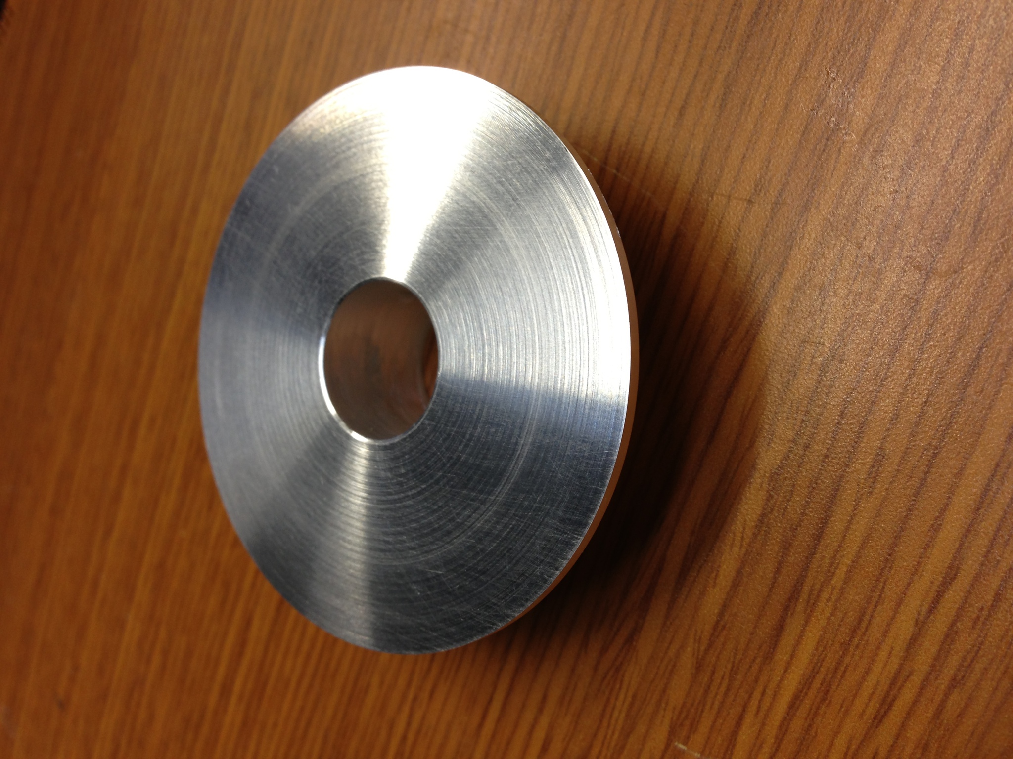
I then made the finish cuts to the exterior and with the boring bar to the interior to get the shape and approximate surface finish I was looking for.
Unfortunately, as I feared, the metal was too brittle to make the bend, and several fins broke off.
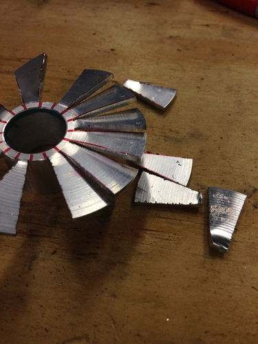
Oh well, at least now I know that method won't work...
I spent some time playing with Aluminium (6061-T6) on my lathe to see if I could make a simple exhaust turbine wheel by separating a disk into fins and twisting them then sanding the edges into a semi-airfoil shape. First I roughed out the general shape I was going for, and drilled the hole through the center (my lathe bed isn't long enough to do so).
I then made the finish cuts to the exterior and with the boring bar to the interior to get the shape and approximate surface finish I was looking for.
Unfortunately, as I feared, the metal was too brittle to make the bend, and several fins broke off.

Oh well, at least now I know that method won't work...
Sunday, January 6. 2013
Dual DAC I+Q Generation and Carrier Modulation
I wanted a simple, easily-interfacable QAM source to test some code I had written for the RTL-SDR, so I put together two small boards: one with two SPI DACs to generate the I and Q inputs, and one board with a single analog QAM modulator on it that takes the carrier, I, and Q signals and outputs the modulated carrier.
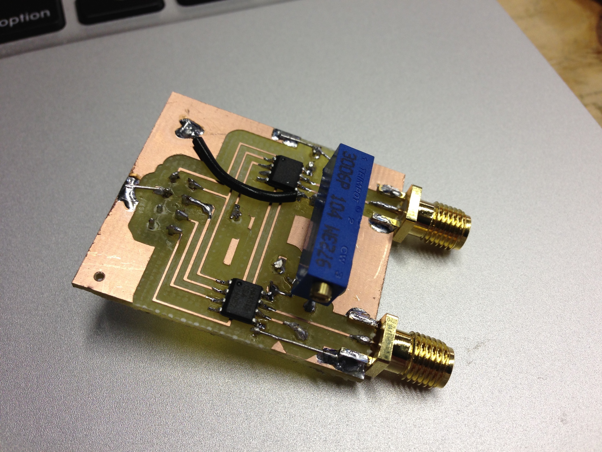
First, I made the dual DAC board with two MAX515's - simple, 10-bit, SPI DACs.
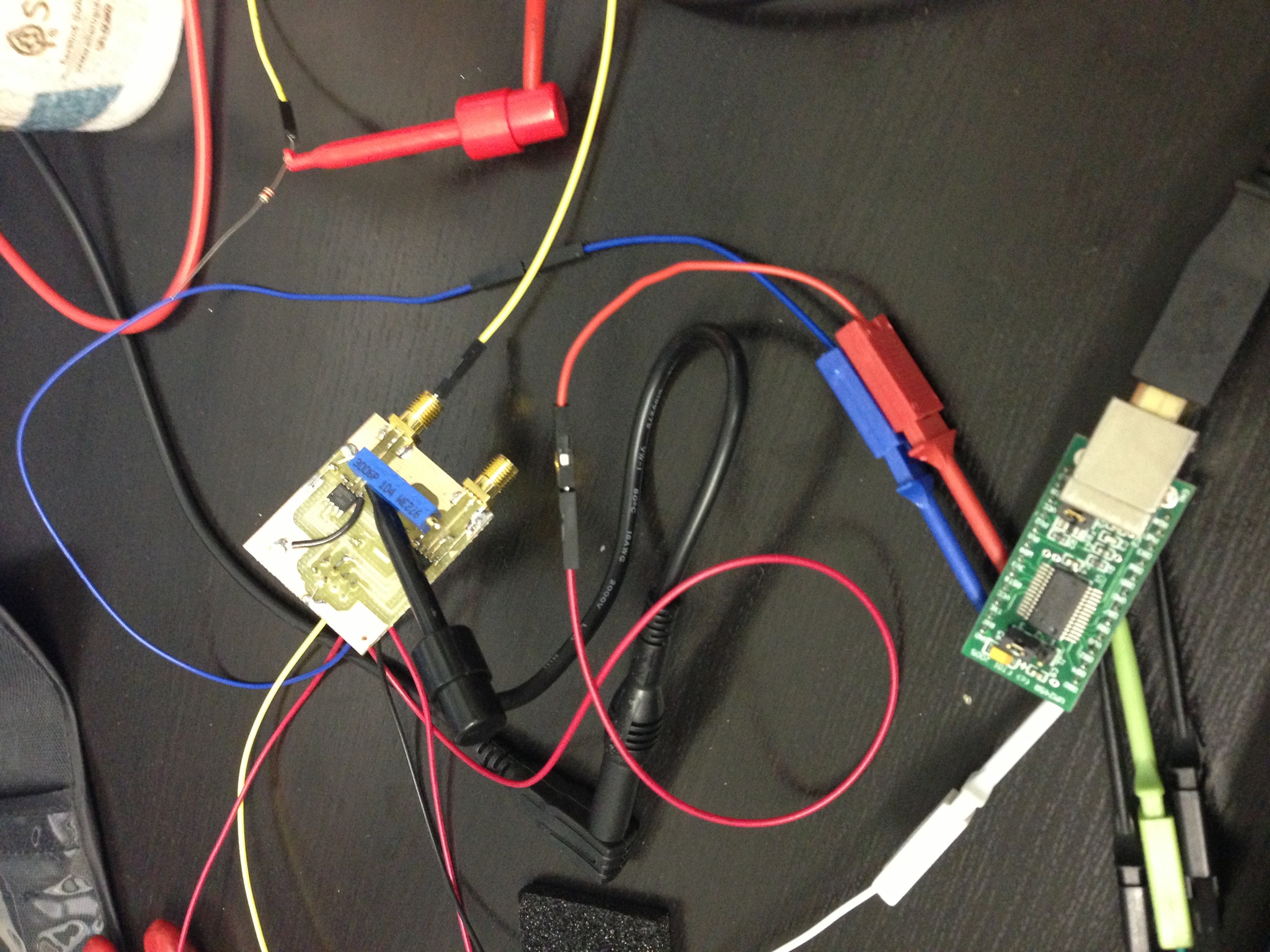
Aesthetically the board was not stunning - I used too large a drill for the through holes, and thus my pads were blown out. However, it was salavgable, so I continued putting it together and testing it by bit-banging the DACs with an FT245R dev board:
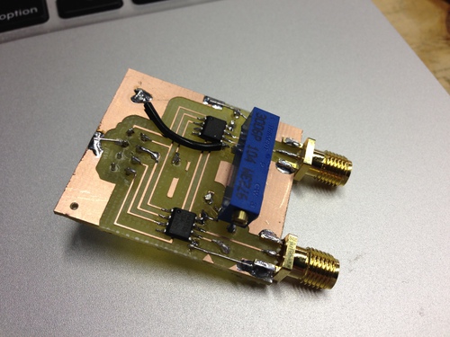
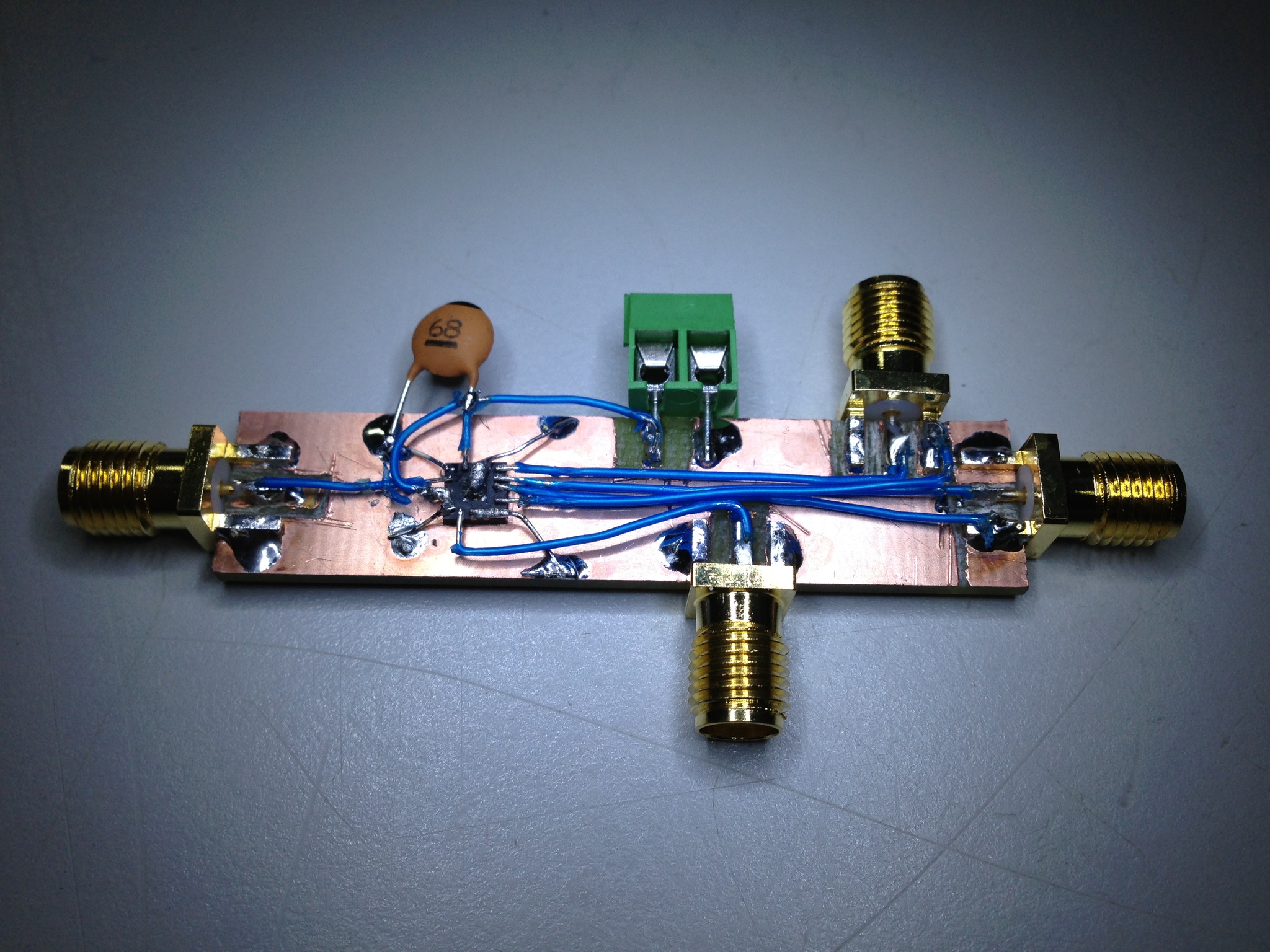
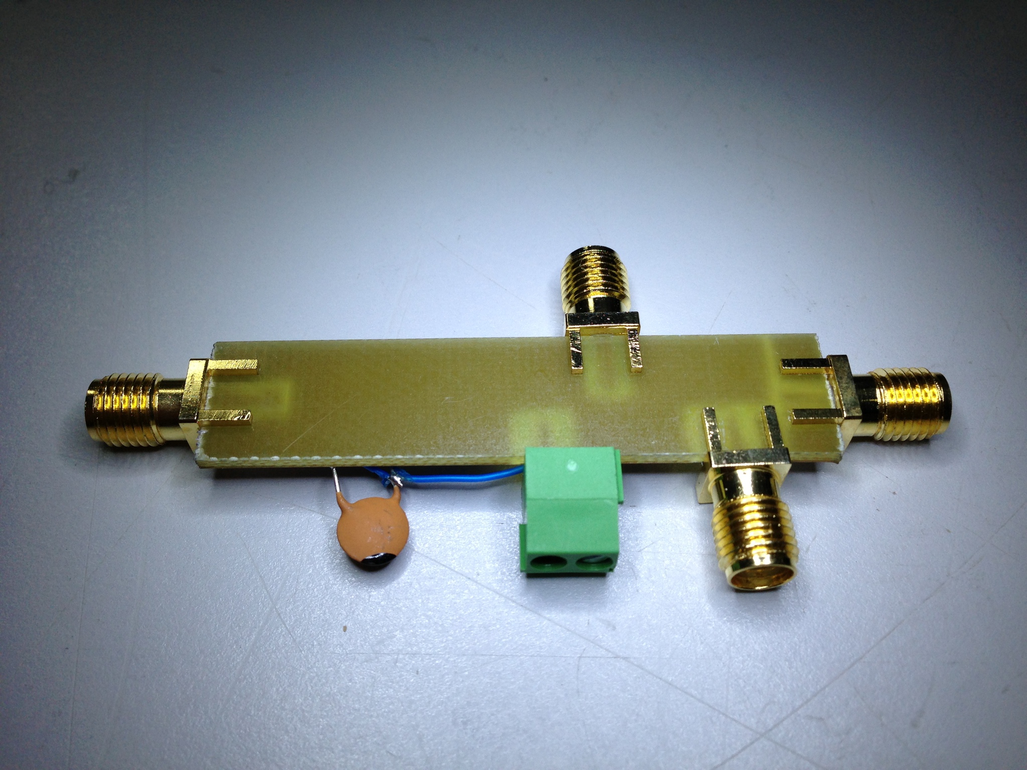
With that working well, I dead-bugged the modulator, a TRF370417 that will handle carrier freqs of 50 MHz through 6 GHz, to another board:

As pretty as that board turned out, it was unfortunately (and predictably) extremely noisy. Oh well, I suppose I will just have to make a proper board for all 3 chips...
First, I made the dual DAC board with two MAX515's - simple, 10-bit, SPI DACs.
Aesthetically the board was not stunning - I used too large a drill for the through holes, and thus my pads were blown out. However, it was salavgable, so I continued putting it together and testing it by bit-banging the DACs with an FT245R dev board:
With that working well, I dead-bugged the modulator, a TRF370417 that will handle carrier freqs of 50 MHz through 6 GHz, to another board:
As pretty as that board turned out, it was unfortunately (and predictably) extremely noisy. Oh well, I suppose I will just have to make a proper board for all 3 chips...
Saturday, December 15. 2012
Reverse Engineering an Audi ECU
The thing that annoys me most about the ECU in my car is that it gives barely any debugging information about sensors and states. It's an older car so some of the sensors started getting a little wacky, but which ones? Fast forward a week and I had decided I needed to pull the code off the ECU to see how it works, then add a few functions of my own. There are a few businesses out there that reflash ECUs for performance increases and such, so if they can do it so can I.
I started by grabbing an ECU for my year and model of car from a junkyard, and opening it up.

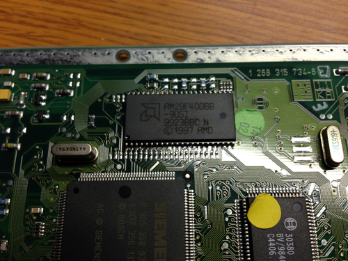
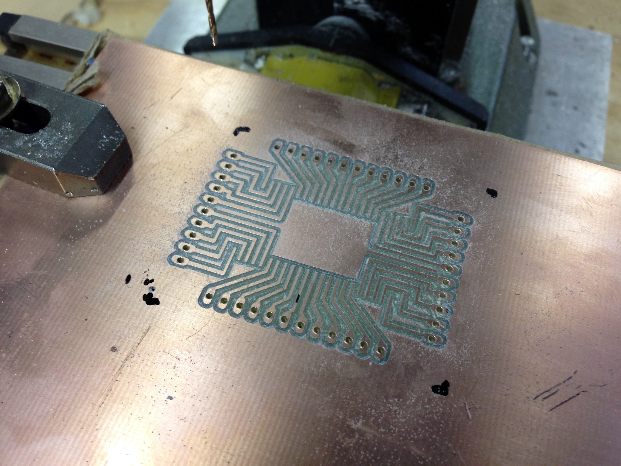
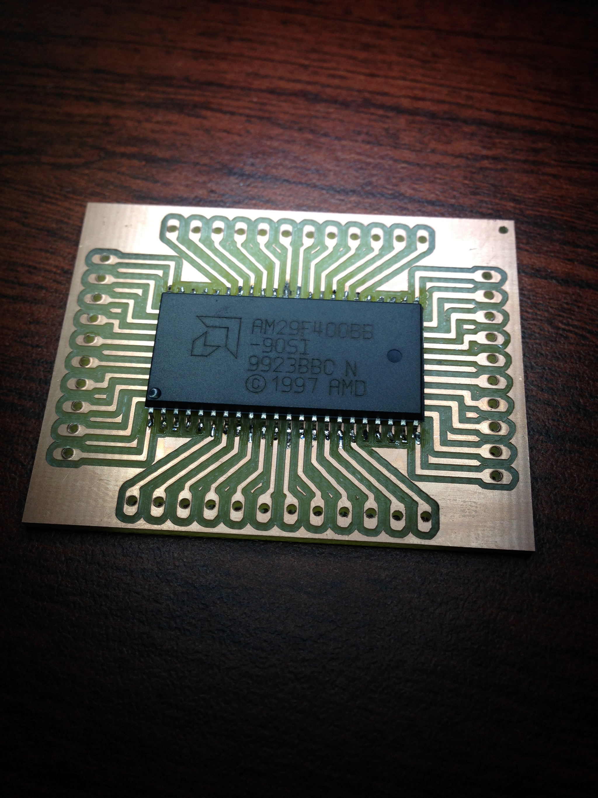
A quick glance shows that it's very simple: a C167 MCU, which loads its code from an Am29F400B flash at boot. The C167 is a great device for cars, as it has a ton of PWM channels and speaks CANBUS natively, and even includes the ability to load code via CANBUS. I was able to quickly find the datasheet and debugging hints documents, as well as a datasheet for the flash itself. Clearly, my next course of action was to yoink the flash and read it (note that in the above pics, I've already desoldered it from the board).
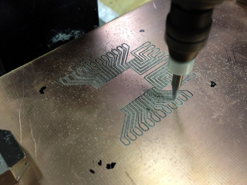
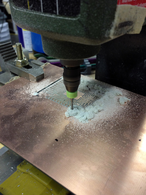
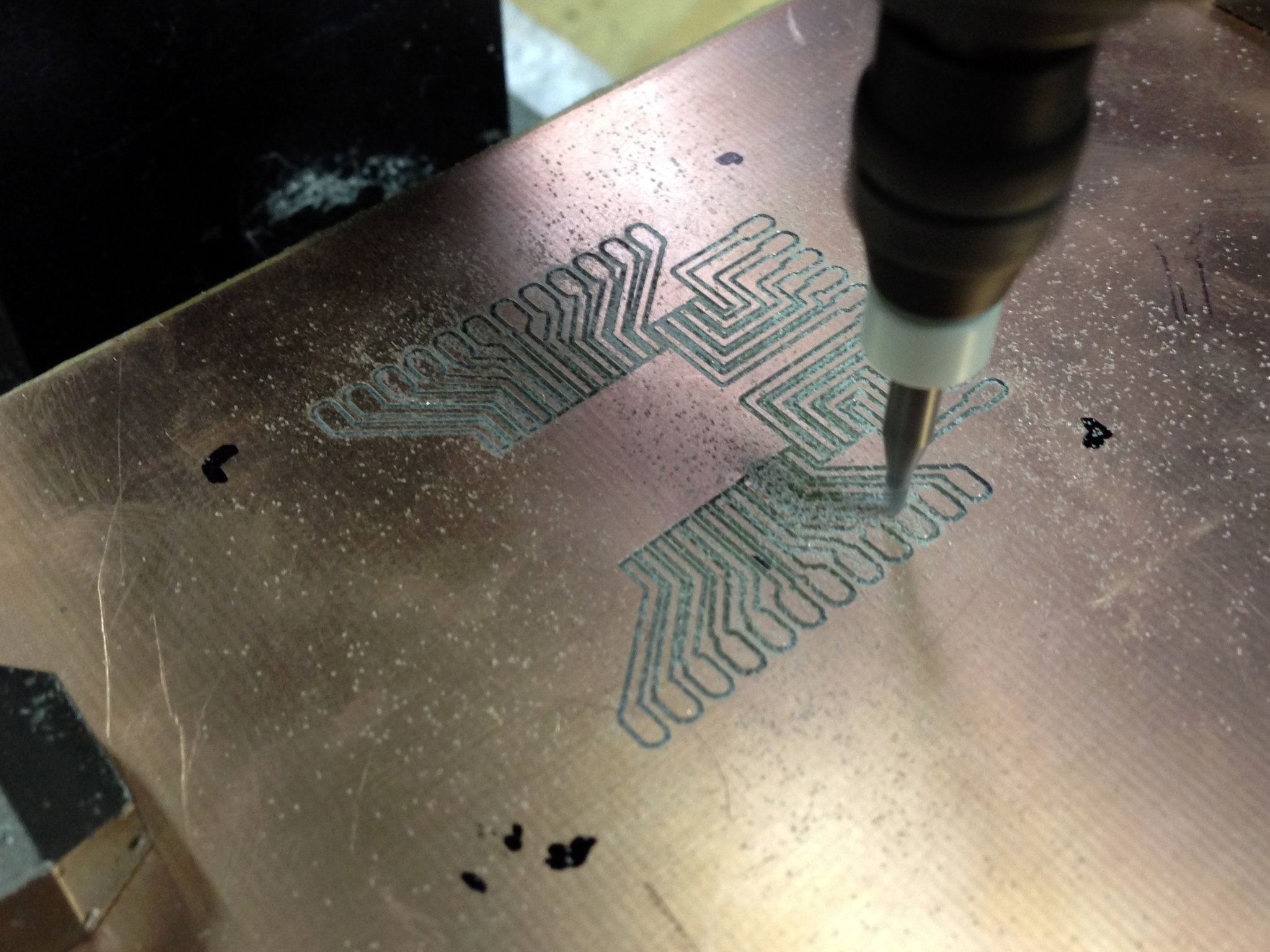
I hacked up a board design to give me easy access to the pins, and cut it using the mill:

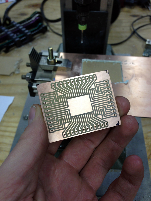
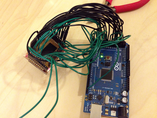
I did my math right and it came out great the first time. I had quite an internal debate about reading the data though- the elegant way to go about it would have been to write a general FPGA memory reader-writer that would also allow me to do passive memory snooping (ie, latch on address changes and record both the address and data value), but I decided to focus on one project at a time and just wrote a few lines of C for an Atmega board I had handy:

It worked nicely! I need to spend some time mapping out the IO addresses, but at first glance, the bootloader has an amusing tamper-protection scheme. The first block of code on the flash loads data into RAM from farther down the flash itself... but adds 1 to each value. Thus, to recover the original instructions, all I had to do was decrement each value by one and pass it into the disassembler again. Epic.
I started by grabbing an ECU for my year and model of car from a junkyard, and opening it up.
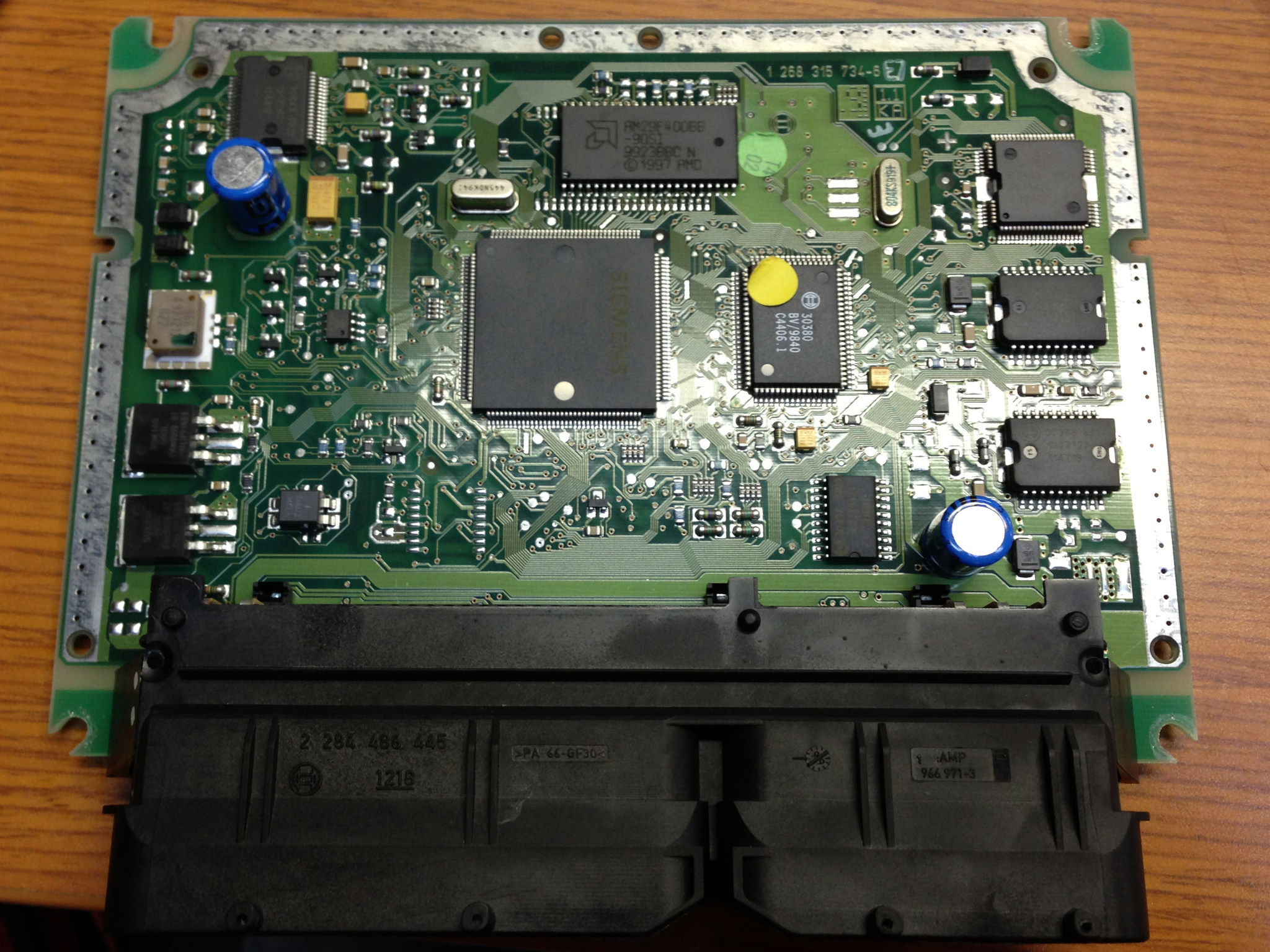
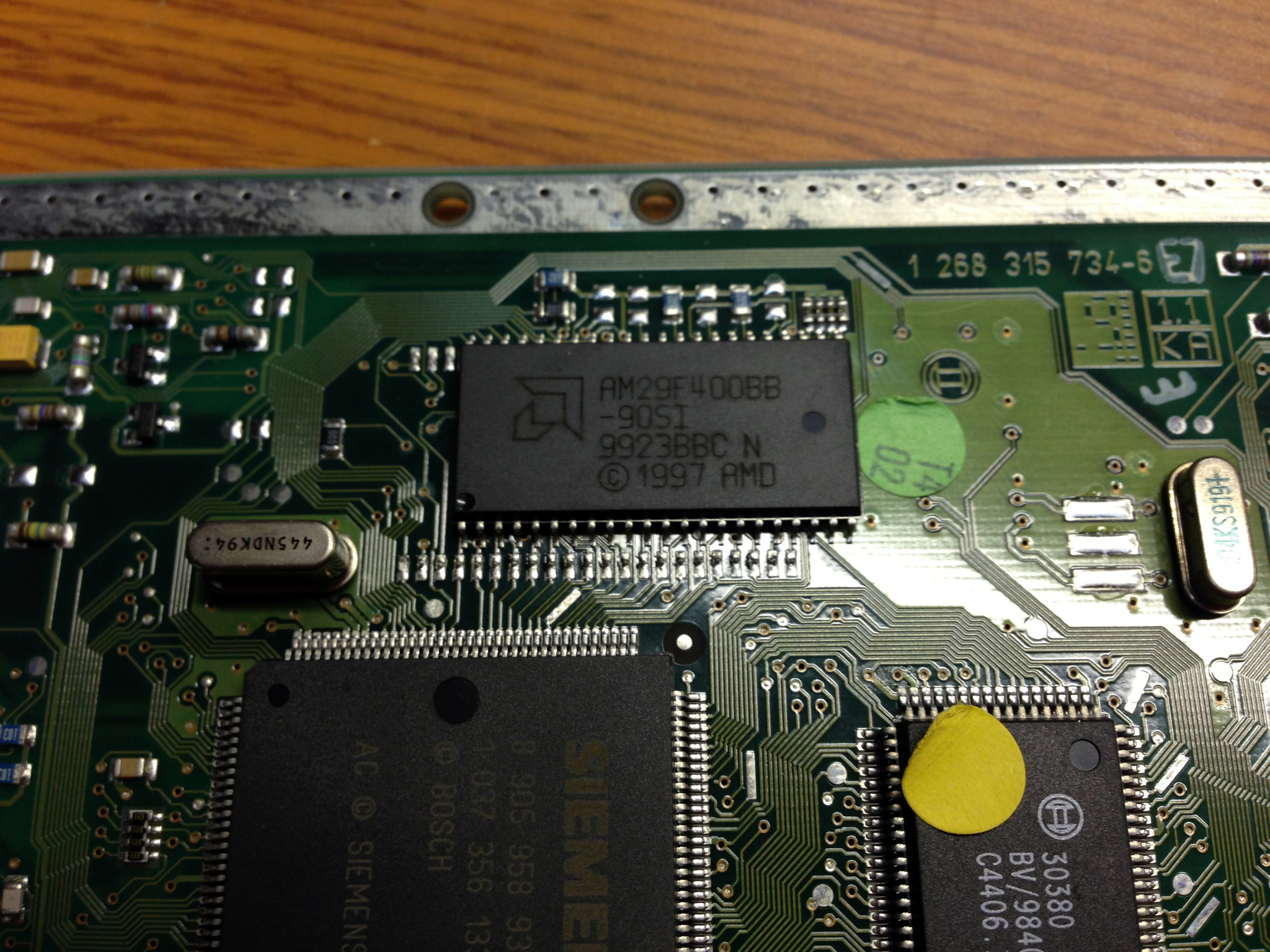
A quick glance shows that it's very simple: a C167 MCU, which loads its code from an Am29F400B flash at boot. The C167 is a great device for cars, as it has a ton of PWM channels and speaks CANBUS natively, and even includes the ability to load code via CANBUS. I was able to quickly find the datasheet and debugging hints documents, as well as a datasheet for the flash itself. Clearly, my next course of action was to yoink the flash and read it (note that in the above pics, I've already desoldered it from the board).
I hacked up a board design to give me easy access to the pins, and cut it using the mill:

I did my math right and it came out great the first time. I had quite an internal debate about reading the data though- the elegant way to go about it would have been to write a general FPGA memory reader-writer that would also allow me to do passive memory snooping (ie, latch on address changes and record both the address and data value), but I decided to focus on one project at a time and just wrote a few lines of C for an Atmega board I had handy:


It worked nicely! I need to spend some time mapping out the IO addresses, but at first glance, the bootloader has an amusing tamper-protection scheme. The first block of code on the flash loads data into RAM from farther down the flash itself... but adds 1 to each value. Thus, to recover the original instructions, all I had to do was decrement each value by one and pass it into the disassembler again. Epic.
Saturday, May 5. 2012
Hybrid Rockets: v2
Inspired by the wild success of the previous rocket engines, I machined some cases and nozzles from aluminium to see what would happen. What happened was exactly what was expected: epic thrust, followed shortly by epic structural failure.
I machined this beautiful nozzle on the lathe and was extremly proud of it. I knew that, being aluminium, it wouldn't last more than a few seconds assuming ignition was acheived, but it sure was awesome until that point.
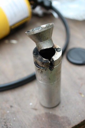
And lo, it failed just like expected (through the thin parts), but not before making an absolutely epic flame plume and a noise I can't quite describe other than LOUD. But check out that ablation!
Since we still had fuels but no more nozzles nor cases, we decided we better burn through a few more home depot plumbing engines. We succeeded wildly at this goal as well.

After that was through, we realized we had the new o2 regulator that might make the 10' black iron 'engines' work a bit better. With much haste, the motor was connected and ignited.


Unfortunately I didn't get any pictures of the actual firing as I was hiding behind the most dense objects I could find, in this case the o2 tanks. Suffice to say the cloud of deathgas was too thick to see through and expansive enough to cover an airport. Great success! We still only got about 1' of the PVC burning, we're going to step up to either multiple o2 injectors, or liquid o2.
I machined this beautiful nozzle on the lathe and was extremly proud of it. I knew that, being aluminium, it wouldn't last more than a few seconds assuming ignition was acheived, but it sure was awesome until that point.

And lo, it failed just like expected (through the thin parts), but not before making an absolutely epic flame plume and a noise I can't quite describe other than LOUD. But check out that ablation!
Since we still had fuels but no more nozzles nor cases, we decided we better burn through a few more home depot plumbing engines. We succeeded wildly at this goal as well.
After that was through, we realized we had the new o2 regulator that might make the 10' black iron 'engines' work a bit better. With much haste, the motor was connected and ignited.
Unfortunately I didn't get any pictures of the actual firing as I was hiding behind the most dense objects I could find, in this case the o2 tanks. Suffice to say the cloud of deathgas was too thick to see through and expansive enough to cover an airport. Great success! We still only got about 1' of the PVC burning, we're going to step up to either multiple o2 injectors, or liquid o2.
Friday, April 27. 2012
Hybrid Rockets: v1
If you've followed my blog for a while (years) you'll note I like rockets. In the more recent years there had been a significant lack of proper exothermic reactions, and this needed to change.
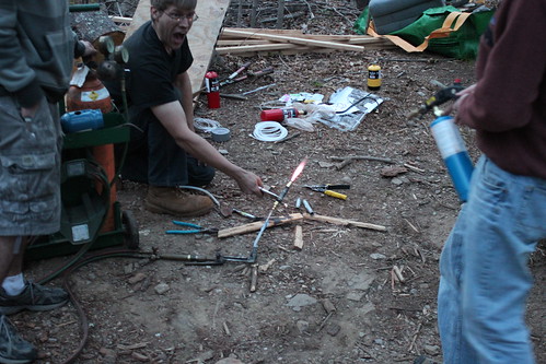
I started matlabbing and thinking of good ways to do liquid-propellant motors, but thought that perhaps I should attempt the more-simple hybrid rocket engines first. On a Saturday morning I hit Home Depot and purchased all the things one needs to make a simple hybrid motor: oxygen, a rubber hose or plastic stock, and enough pipe fittings to put a small hole on the end.
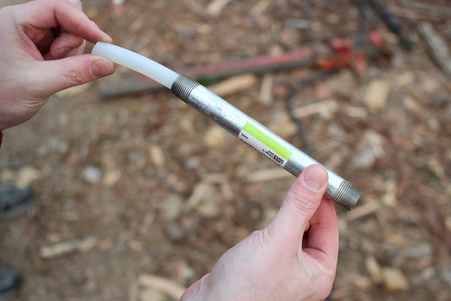
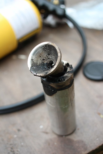
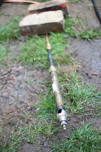
Here you can see I have some rubber hose (the fuel) inside a metal pipe. When the oxygen passes through the hose, the pair REALLY want to burn. Below, the whole setup assembled:
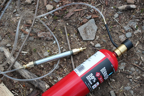
The home depot ox tank comes with a tiny regulator, which later became a problem. However the setup on a whole is extremely simple. Ignition was achieved by inserting a bit of rubber through the nozzle and touching the tube inside, flowing a small amount of ox through the system, and lighting the rubber with a torch. Worked first time!

As stated, we soon needed more oxygen. Luckily Ken had his welding setup on hand....

As you can see from Ken's face, much more mass flow happened...
Of course, things quickly progressed from there. Ken noted he had an idea, and quickly returned with a 10' length of black iron pipe and a similar piece of PVC that fit inside. He drilled holes in two caps, threaded them on, and we were ready to roll.

Fortunately enough for us, we could only get enough oxygen flow for about 6" of PVC to burn. Regardless, that produced a TON of black deathsmoke, heat, and noise. Had we had a larger flow regulator, the thing would have killed everyone in town. We'll have to order one for next time.
I started matlabbing and thinking of good ways to do liquid-propellant motors, but thought that perhaps I should attempt the more-simple hybrid rocket engines first. On a Saturday morning I hit Home Depot and purchased all the things one needs to make a simple hybrid motor: oxygen, a rubber hose or plastic stock, and enough pipe fittings to put a small hole on the end.
Here you can see I have some rubber hose (the fuel) inside a metal pipe. When the oxygen passes through the hose, the pair REALLY want to burn. Below, the whole setup assembled:
The home depot ox tank comes with a tiny regulator, which later became a problem. However the setup on a whole is extremely simple. Ignition was achieved by inserting a bit of rubber through the nozzle and touching the tube inside, flowing a small amount of ox through the system, and lighting the rubber with a torch. Worked first time!
As stated, we soon needed more oxygen. Luckily Ken had his welding setup on hand....
As you can see from Ken's face, much more mass flow happened...
Of course, things quickly progressed from there. Ken noted he had an idea, and quickly returned with a 10' length of black iron pipe and a similar piece of PVC that fit inside. He drilled holes in two caps, threaded them on, and we were ready to roll.
Fortunately enough for us, we could only get enough oxygen flow for about 6" of PVC to burn. Regardless, that produced a TON of black deathsmoke, heat, and noise. Had we had a larger flow regulator, the thing would have killed everyone in town. We'll have to order one for next time.
Monday, February 15. 2010
Jet Powered Hovercraft
Chris and I decided we needed to build a propane powered jet engine using a turbo from a car. Given my previous successes with hovercrafts, of course we needed to step the game up.
Our combustion chamber takes air from the compressor, swirls it around with liquid propane, then burns it, creating a huge expansion of the inputs. The gases then pass out into the turbine section of the turbo, spinning the compressor faster, and so on. The brass nozzle you see is the propane connection. The sparkplug is to start the combustion, but the flame is self-sustaining once it's running.
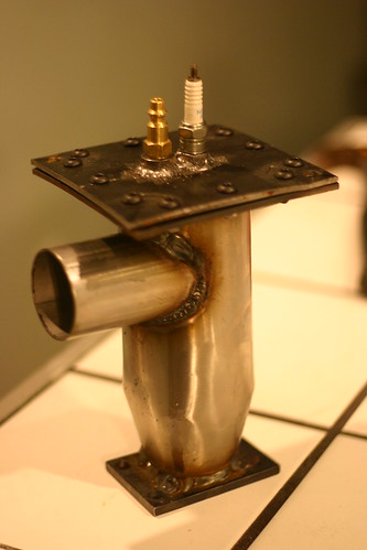
We rigged the combustion chamber to the output of the shop vac, connected the spark coils, and let a little gas flow. Much to our surprise, a significant roar was produced! We were even more pleased when the roar continued after we switched off the sparkplug. Below, Eric inspects the turbo.

When we put it all together, the unit was spinning at upwards of 120 krpm, and blasting the rhododendrons around across the yard. We also used it for snow clearing.
While we still had it running (ie before it was scavenged for parts), two exciting things happened. Once, when we drilled out the propane fittings to get more gas through. This made the engine run at a higher compression of course. Right as Ken reached across the motor to poke a gauge, the cold air manifold from the compressor separated from the combustion chamber, and the resulting gas instantly melted all the hair off Ken's arm. However perhaps more amusing was the time the bearing's oil seal failed during a full-thrust run. 60psi hot, thin motor oil sprayed into the turbine housing and instantly turned to smoke. The sheer amount of black death coming out the back of that jet engine is an image I won't soon forget. epic.
Our combustion chamber takes air from the compressor, swirls it around with liquid propane, then burns it, creating a huge expansion of the inputs. The gases then pass out into the turbine section of the turbo, spinning the compressor faster, and so on. The brass nozzle you see is the propane connection. The sparkplug is to start the combustion, but the flame is self-sustaining once it's running.
We rigged the combustion chamber to the output of the shop vac, connected the spark coils, and let a little gas flow. Much to our surprise, a significant roar was produced! We were even more pleased when the roar continued after we switched off the sparkplug. Below, Eric inspects the turbo.
When we put it all together, the unit was spinning at upwards of 120 krpm, and blasting the rhododendrons around across the yard. We also used it for snow clearing.
While we still had it running (ie before it was scavenged for parts), two exciting things happened. Once, when we drilled out the propane fittings to get more gas through. This made the engine run at a higher compression of course. Right as Ken reached across the motor to poke a gauge, the cold air manifold from the compressor separated from the combustion chamber, and the resulting gas instantly melted all the hair off Ken's arm. However perhaps more amusing was the time the bearing's oil seal failed during a full-thrust run. 60psi hot, thin motor oil sprayed into the turbine housing and instantly turned to smoke. The sheer amount of black death coming out the back of that jet engine is an image I won't soon forget. epic.
Sunday, April 8. 2007
Current Happenings
Monday, April 2. 2007
New Z Axis Motor
Sunday, March 25. 2007
CNC Explosions and Rockets
I’ve been using the mill succesfully for a few weeks now making several PCBs. It’s really been great being able to design a board and have it in my hand within an hour. Unfortunatly, the Z-axis motor appears to have bit the dust. I came back from the other side of the shop to some bad-sounding noises, and the bit was quite embedded in the pcb… so no boards until I can take a look at that.
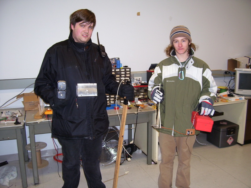
I made a few boards for my friends MQP (a kind of senior thesis project at WPI). His team is making a large rocket with an onboard computer and needed a wireless control. I designed and built him a transmitter and receiver from Lynx chips. They seem to work amazingly… more on that after the launch.
Ryan and I just after testing the range. We look oh-so-happy:
Very slow progress continues on the new 44″x22″ mill, but what little time I’m not doing school work I’m doing the rocket project. Hopefully things will clear up a bit soon.
Tuesday, January 23. 2007
CNC Machine Works!
Update 2012: I ended up purchasing real steppers so that I can actually get things done in a reasonable amount of time. After the controller I made melted again, I ended up purchasing an $80 chinese model that has been working well ever since. I have the mill at the shop and still use it to make parts for work. That said, this was the FIRST thing I ever machined myself, so yes, it looks horrible. It does work though.
I’ve wanted to build a CNC machine for about 2 years now (since I found out what one was). Mostly I wanted one to make robot parts and such, since I always had problems machining them by hand. This year I finally had the tools available to me to fabricate the parts neccesary to convert a standard mill to CNC. I got a wicked small Proxxon MF-70 for christmas (thanks parents!), and went about the process.
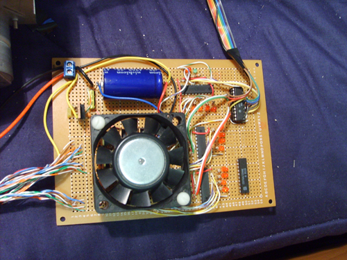
My friend Ken had 3 matched unipolar stepper motors from Cannon scanners that he donated to the cause (to be fair, I agreed to make him PCBs with the mill). I first built a controller that converts steps and direction signals from the parallel port to stepper control signals. First, the direction and step signals are converted to the correct stepper high and low states for the stepper motors by 3 L297 chips from ST Micro. I really do love these drivers, and use them in pretty much any project involving a stepper. Since the logic of these chips can’t sink or source 3 amps, I use 12 TIP102 transistors (4 per motor, 1 per coil wire) to provide switching to the motors. Each motors’ common line is hooked to the +12v supply from the board, and each control line is ground-side switched by the transistor.
The only other things on the board are a giant filter capacitor (stepper motors are very spiky things), a 5v regulator, a P3 fan to cool the transistors, and some pretty LEDs to a) let me see which liens are changing in order to debug things and b) look cool. (Click on any picture for a larger view)
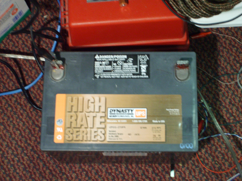
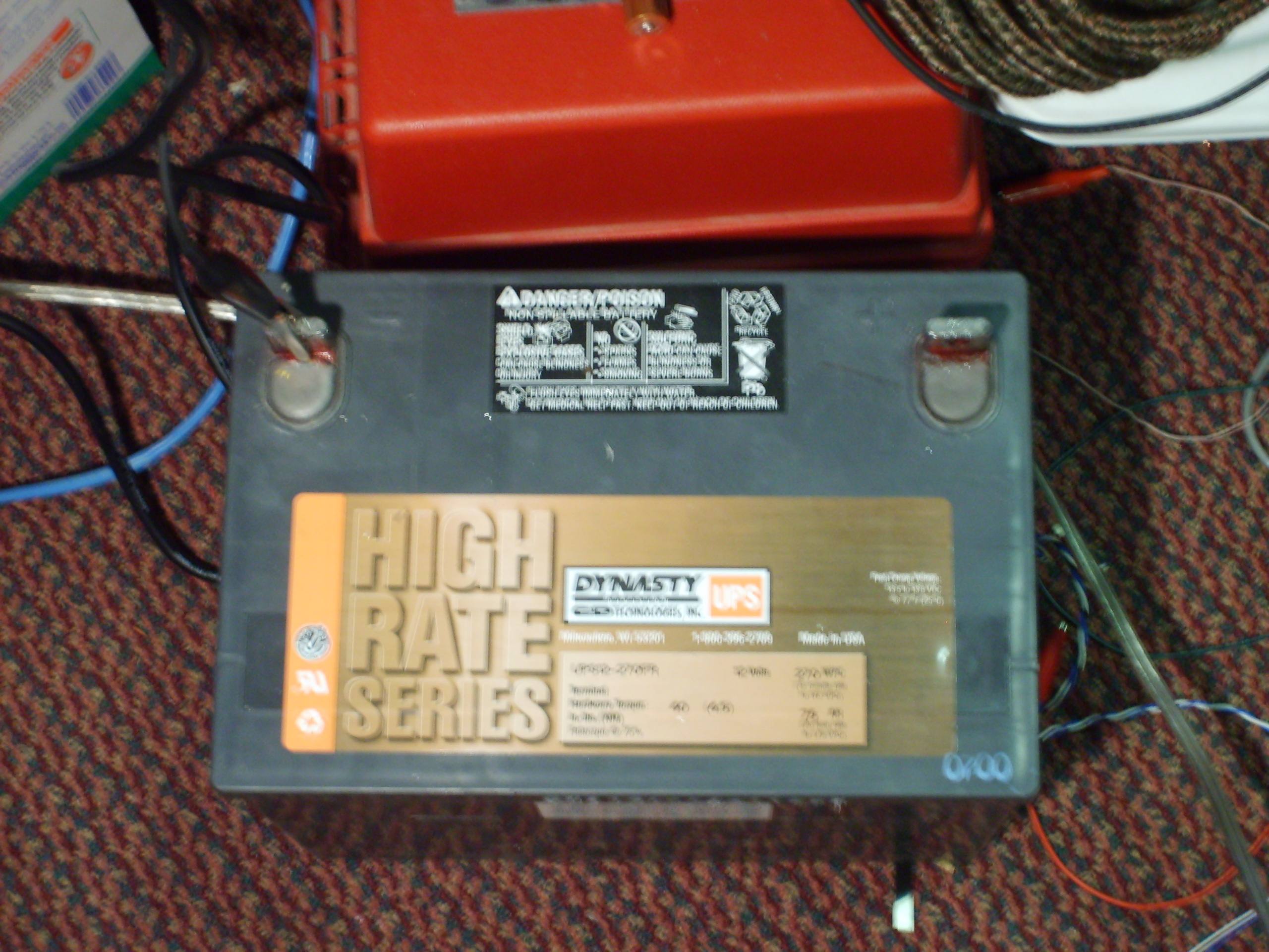
The whole unit is currently powered by a giant 12v lead acid battery. I guess I’ll eventually have to find a way to charge this thing or build a power supply, but I had this sitting around and didn’t feel like making a supply. I’ve used the mill quite a bit so far and it hasn’t noticably discharged. Update 2012: Still using that lead acid
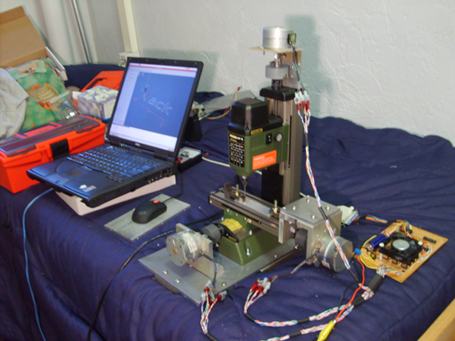
So… here it is And yes, that is my bed. Note that a CNC mill in your bed makes it not very condusive to sleeping… but some things can be sacrificed.
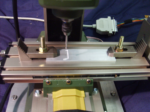
Close up of the front: (Yes, that's a ball tool for a dremel.. don't worry I did eventually learn how to machine things properly)
The X-axis controller:

Y-axis:
Z-axis:

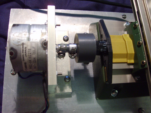
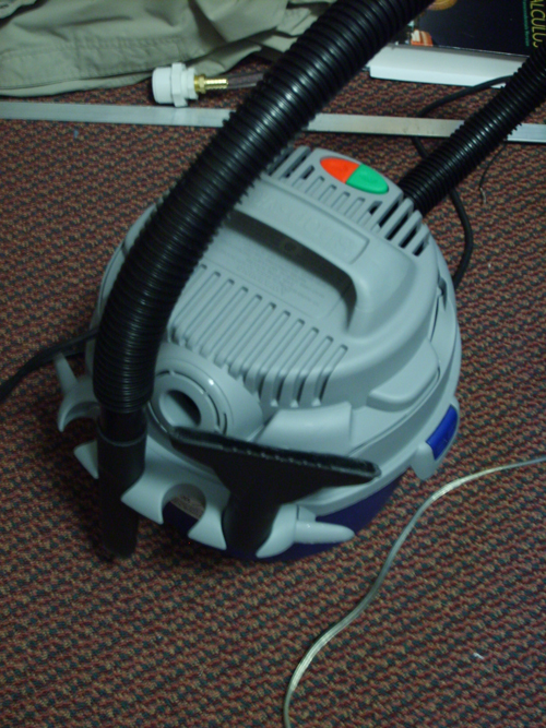
I got this sweet 2.5 horsepower 2.5 gallon shop vac. It fits right next to the spindle and moves up and down with it, so it sucks up all the aluminium, as well as cools the bit fairly well. It effectively keep aluminium off of my bed.
This is really the best thing I’ve made so far, but I hope to get time to work on some cooler projects shortly in the future.

I’ve wanted to build a CNC machine for about 2 years now (since I found out what one was). Mostly I wanted one to make robot parts and such, since I always had problems machining them by hand. This year I finally had the tools available to me to fabricate the parts neccesary to convert a standard mill to CNC. I got a wicked small Proxxon MF-70 for christmas (thanks parents!), and went about the process.
My friend Ken had 3 matched unipolar stepper motors from Cannon scanners that he donated to the cause (to be fair, I agreed to make him PCBs with the mill). I first built a controller that converts steps and direction signals from the parallel port to stepper control signals. First, the direction and step signals are converted to the correct stepper high and low states for the stepper motors by 3 L297 chips from ST Micro. I really do love these drivers, and use them in pretty much any project involving a stepper. Since the logic of these chips can’t sink or source 3 amps, I use 12 TIP102 transistors (4 per motor, 1 per coil wire) to provide switching to the motors. Each motors’ common line is hooked to the +12v supply from the board, and each control line is ground-side switched by the transistor.
The only other things on the board are a giant filter capacitor (stepper motors are very spiky things), a 5v regulator, a P3 fan to cool the transistors, and some pretty LEDs to a) let me see which liens are changing in order to debug things and b) look cool. (Click on any picture for a larger view)

The whole unit is currently powered by a giant 12v lead acid battery. I guess I’ll eventually have to find a way to charge this thing or build a power supply, but I had this sitting around and didn’t feel like making a supply. I’ve used the mill quite a bit so far and it hasn’t noticably discharged. Update 2012: Still using that lead acid
So… here it is And yes, that is my bed. Note that a CNC mill in your bed makes it not very condusive to sleeping… but some things can be sacrificed.
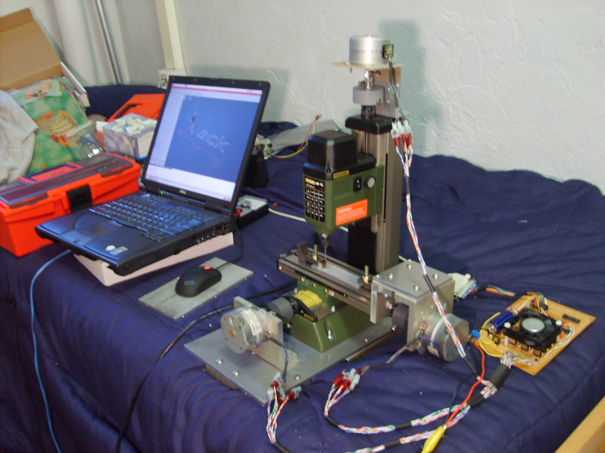

Close up of the front: (Yes, that's a ball tool for a dremel.. don't worry I did eventually learn how to machine things properly)
The X-axis controller:
Y-axis:

Z-axis:
I got this sweet 2.5 horsepower 2.5 gallon shop vac. It fits right next to the spindle and moves up and down with it, so it sucks up all the aluminium, as well as cools the bit fairly well. It effectively keep aluminium off of my bed.
This is really the best thing I’ve made so far, but I hope to get time to work on some cooler projects shortly in the future.
Thursday, April 27. 2006
Electric Gokart
Update: Now that I actually know how to machine things, I’m going to revamp the Kart next time I’m home. Real bearings for the steering assembly, pedals and a floorboard, etc. Should be interesting…
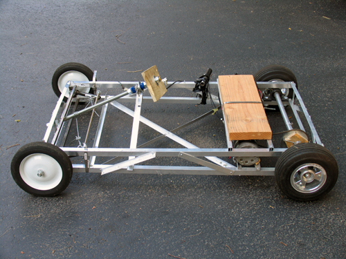
I built this “Kart” basically because I wanted to see if I was good at building large (or larger than normal) things, and to satisfy a “project” requirment for my physics class. While most people built small electronics projects on breadboards, I built this. People were pretty surprised.
Update to the update: The frame got turned into a trike for the hang glider, and the motor got imported to a scooter. Both were epic.
Frame
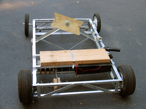
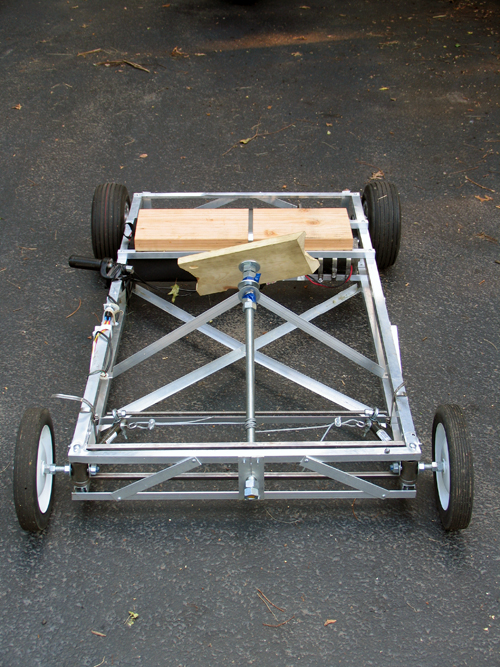
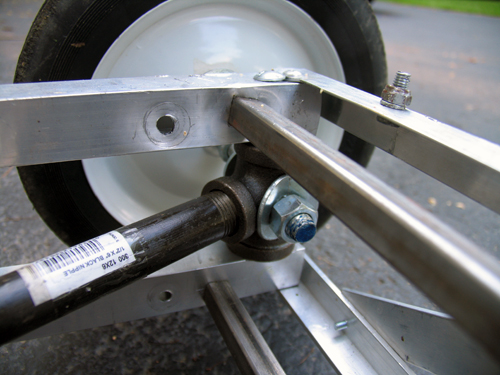
The frame was designed (in my head, since I can’t draw) to be very light, but hopefully still fairly strong. Four 1″ square aluminum stock bars run the length of the frame as 4 edges of a box. Each side of this “box” is then held the proper distance apart by perpendicular flat stock and held rigid by 2 opposite-direction diagnals of either flat stock or square stock.
The cross peices that go between the frame sides in the front are 1/2″ inch steel square stock. It is absolutly key that these side sections stay the same distance apart, as they control the cambre of the wheels. The steel is held in place by threaded rod. (I would have used aluminum, but Home Depot is terrible at restocking and never had enough.)
The front wheels are lame garden wheels from Home Depot (about $8 each) with built in bearings. It remains to be seen how long the bearings will last, but they haven’t fallen out yet…
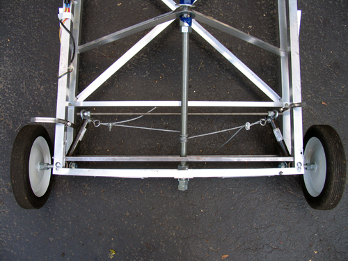
Steering
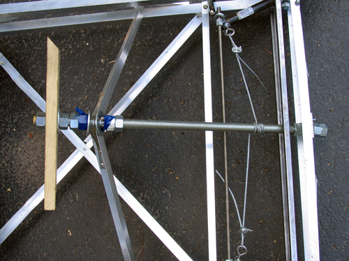
The steering idea was conceived by Sean Manix and Joe Gage in a gravity-powered car we built long ago. I modified the design somewhat to work here. Basically, the system works as a rack and pinion system does, minus the rack and the pinion. The tierod keeps outward tension on the steering arms so that they stay the proper distance apart and the wheels stay parallel; the wire pulls the whole sytem to one side or the other to steer while at the same time keeping tension on the steering arms so they stay on the tierod.
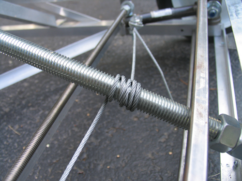
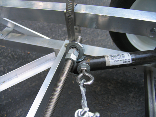
Yes, the steering arms are made of plumbing equipment.
Inside those plumbing T’s, bolts come in from both square sections of frame. Roller skate bearings (that I had around and just happened to fit) go over the bolts and space the plumbing to sit in the center. I then put the T’s on the drill press and put the 1/2″ holes in them. Let me tell you, that was scary. The bit has a tendancy to catch coming out the other side, so the whole T arm unit spins around the bit fast enough to break your arm.
As inaccurate as this looks, it actual is very smooth and tight. The steering feels nice while youre driving.
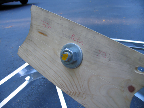
…don’t ask, it’s a school thing somebody wrote. But yes, that is the “steering plank”.
Drive Train
The motor is from an electric scooter. It’s 750 Watts… in pure energy, 1 horsepower = 746 Watts, but I think here the 750w describe amount of power the motor pulls from the batteries, not the mechanical energy put out. Since the motor is likely only moderatly efficient, I’d say it’s in the half-horsepower range.
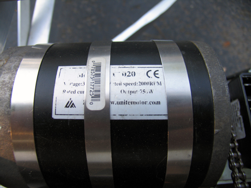
My girlfriend Erica is building a kart on the same design as this one. I helped her get her motor… hers is 1200w. I think I’ll still be able to beat her once I figure out how to put some sort of transmission on this thing. The chain and rear cog are from the scooter too.
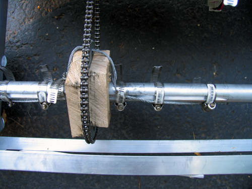
The bain of my existance… the blocks holding the rear sproket are badly made and thus wobble. The axle (1″) has a keyway in it, and the sproken has a 2″ hole. Logically, we’d make spacers to simply hold it in the center, and the spacers would fit the keyway to spin it. I built two of these out of hard wood. I cut the 1″ and keyway with a coping saw (which was a hard process), screwed the whole thing together, and slapped the chain on. It looked perfect. As soon as I touched the throttle, the keyways sheared off (wood doesn’t deal with shear stress very well) and the whole unit simply spun.
Despite efforts to make some sort of key, each time something would slip or shear off as I don't have access to any sort of metal shop. Thus, the steal cable goes through the hole in the sproket and get band clamped to the axle. The wood simply acts to keep the sproket in the right place, and the cable deals with transfering the torque to the axle. It’s ugly, and the chain pops off occasionally. I need to make some sort of mount from aluminum…
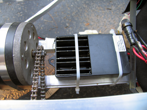
This is basically just a large version of the electronic speed controller in a remote control car. Rather than having huge variable resistors, the “ESC” as its called simply pulses the motor very quickly, and by varying how many of these pulses are “on” and “off” we vary the speed.
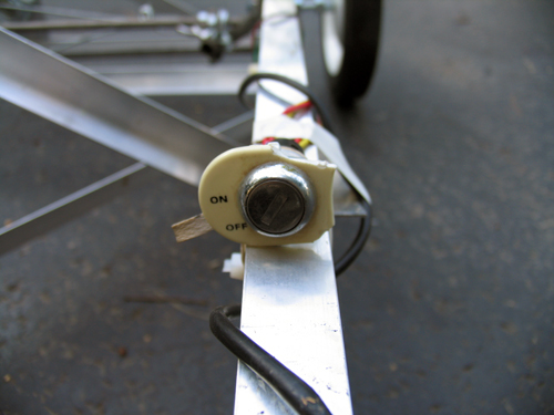
Ignition… because I can.
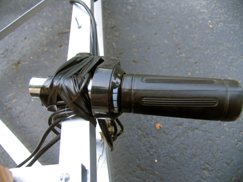
The throttle from the scooter. Yes, it is taped to the side. I haven’t had a chance to fasion some sort of pedal yet.
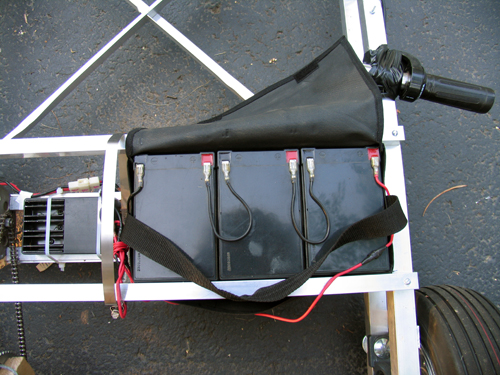
Three 7 Ah lead acid batteries power this 36v beast… they’re heavy.
Final Thoughts
In case you were wondering, there are no brakes. I haven’t gotten to that yet. But hey, when I get to the transmission and the throttle pedal, perhaps a brake might appear.
I built this “Kart” basically because I wanted to see if I was good at building large (or larger than normal) things, and to satisfy a “project” requirment for my physics class. While most people built small electronics projects on breadboards, I built this. People were pretty surprised.
Update to the update: The frame got turned into a trike for the hang glider, and the motor got imported to a scooter. Both were epic.
Frame
The frame was designed (in my head, since I can’t draw) to be very light, but hopefully still fairly strong. Four 1″ square aluminum stock bars run the length of the frame as 4 edges of a box. Each side of this “box” is then held the proper distance apart by perpendicular flat stock and held rigid by 2 opposite-direction diagnals of either flat stock or square stock.
The cross peices that go between the frame sides in the front are 1/2″ inch steel square stock. It is absolutly key that these side sections stay the same distance apart, as they control the cambre of the wheels. The steel is held in place by threaded rod. (I would have used aluminum, but Home Depot is terrible at restocking and never had enough.)
The front wheels are lame garden wheels from Home Depot (about $8 each) with built in bearings. It remains to be seen how long the bearings will last, but they haven’t fallen out yet…
Steering
The steering idea was conceived by Sean Manix and Joe Gage in a gravity-powered car we built long ago. I modified the design somewhat to work here. Basically, the system works as a rack and pinion system does, minus the rack and the pinion. The tierod keeps outward tension on the steering arms so that they stay the proper distance apart and the wheels stay parallel; the wire pulls the whole sytem to one side or the other to steer while at the same time keeping tension on the steering arms so they stay on the tierod.
Yes, the steering arms are made of plumbing equipment.
Inside those plumbing T’s, bolts come in from both square sections of frame. Roller skate bearings (that I had around and just happened to fit) go over the bolts and space the plumbing to sit in the center. I then put the T’s on the drill press and put the 1/2″ holes in them. Let me tell you, that was scary. The bit has a tendancy to catch coming out the other side, so the whole T arm unit spins around the bit fast enough to break your arm.
As inaccurate as this looks, it actual is very smooth and tight. The steering feels nice while youre driving.
…don’t ask, it’s a school thing somebody wrote. But yes, that is the “steering plank”.
Drive Train
The motor is from an electric scooter. It’s 750 Watts… in pure energy, 1 horsepower = 746 Watts, but I think here the 750w describe amount of power the motor pulls from the batteries, not the mechanical energy put out. Since the motor is likely only moderatly efficient, I’d say it’s in the half-horsepower range.
My girlfriend Erica is building a kart on the same design as this one. I helped her get her motor… hers is 1200w. I think I’ll still be able to beat her once I figure out how to put some sort of transmission on this thing. The chain and rear cog are from the scooter too.
The bain of my existance… the blocks holding the rear sproket are badly made and thus wobble. The axle (1″) has a keyway in it, and the sproken has a 2″ hole. Logically, we’d make spacers to simply hold it in the center, and the spacers would fit the keyway to spin it. I built two of these out of hard wood. I cut the 1″ and keyway with a coping saw (which was a hard process), screwed the whole thing together, and slapped the chain on. It looked perfect. As soon as I touched the throttle, the keyways sheared off (wood doesn’t deal with shear stress very well) and the whole unit simply spun.
Despite efforts to make some sort of key, each time something would slip or shear off as I don't have access to any sort of metal shop. Thus, the steal cable goes through the hole in the sproket and get band clamped to the axle. The wood simply acts to keep the sproket in the right place, and the cable deals with transfering the torque to the axle. It’s ugly, and the chain pops off occasionally. I need to make some sort of mount from aluminum…
This is basically just a large version of the electronic speed controller in a remote control car. Rather than having huge variable resistors, the “ESC” as its called simply pulses the motor very quickly, and by varying how many of these pulses are “on” and “off” we vary the speed.
Ignition… because I can.
The throttle from the scooter. Yes, it is taped to the side. I haven’t had a chance to fasion some sort of pedal yet.
Three 7 Ah lead acid batteries power this 36v beast… they’re heavy.
Final Thoughts
In case you were wondering, there are no brakes. I haven’t gotten to that yet. But hey, when I get to the transmission and the throttle pedal, perhaps a brake might appear.
Saturday, November 6. 2004
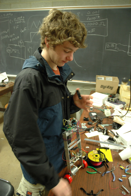
The Balancing Bot
I was looking around for a new project one day, when nBot caught my attention. I knew that balancing robots were hard (look how much the segway costs!), but the more I thought, the more I knew I had to try. [pics missing]
I am yet to have it balance indefinatly, at which point I will write a whole paper about doing this. However right now, I will just list the various versions, and how well they worked.
Version 1
This was (obviously) the first version. It was about 4 feet tall. I found that my motors move way too slowly to keep a bot this size up. Thus we went to the next version.
Version 2
I chopped off about a foot and a half, so the bot is now 2 and a half feet. I figured that the bot would be able to right itself better since the moment arm is shorter, thus the same linear speed is a much faster angular speed. It now stands for about 10 seconds, but inevitably still falls.
Version 2.5
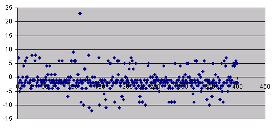
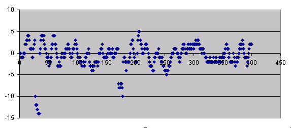
I found that the problems were due to inaccurate readings in the IR sensors. So I made a running array of the last 8 values, and used the average of them for the calulation. This didn’t quite work, either. Look at these graphs:
For both of these tests, the IR sensor was stationary in a vise pointed at a wall. That should give you some idead how inaccurate it is. The first is without my fix:
And with the fix:
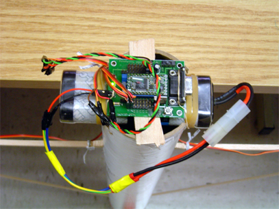
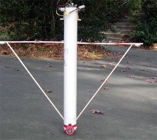
Version 3
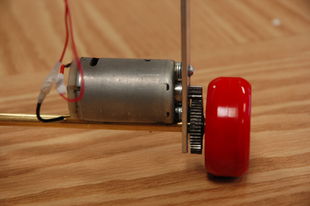
I gave up on the IR sensors: now I’m using sonar. It’s much more accurate, but I only have one. So the bot now balances for about 20 seconds, but the wheels simply can’t go fast enough to catch up if it gets moving more than a few inches per second. I hope to make some new wheels today.
Version 3.1
I ran over to the wood shop (we don’t have a metal shop) and made some bigger wheels… it seemed to me that the servos had quite a bit of torque, but didn’t go fast enough. Thus, increase the radius, we increase the distance traveled per revolution.
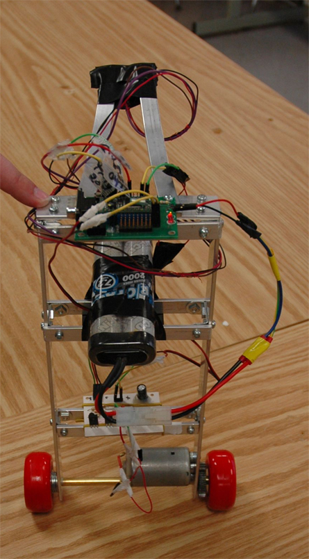
Version 4.0
The whole bot has been completly redesigned. The wheels of wood were not prefectly true, and thus wobbled way too much to balance properly. Also, the body was not ideal, the motors weren’t good enough, it was too tall, heavy in the wrong places….
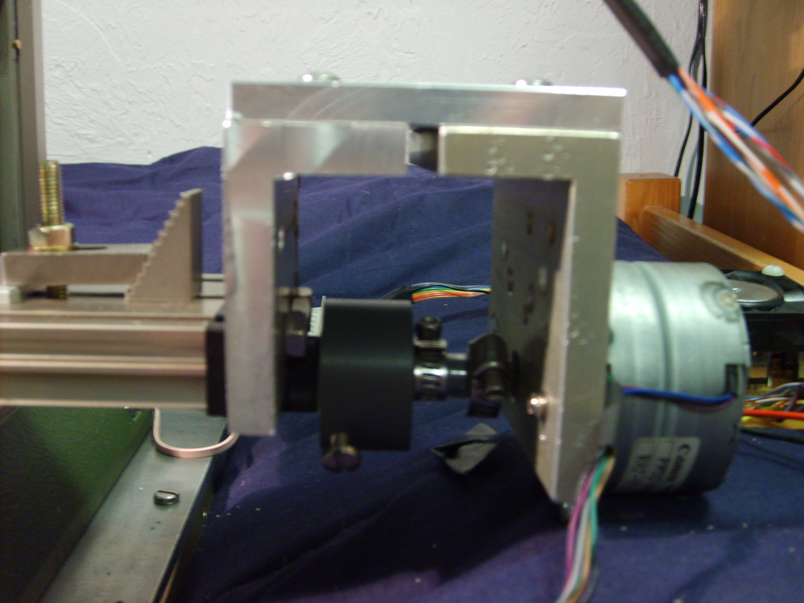
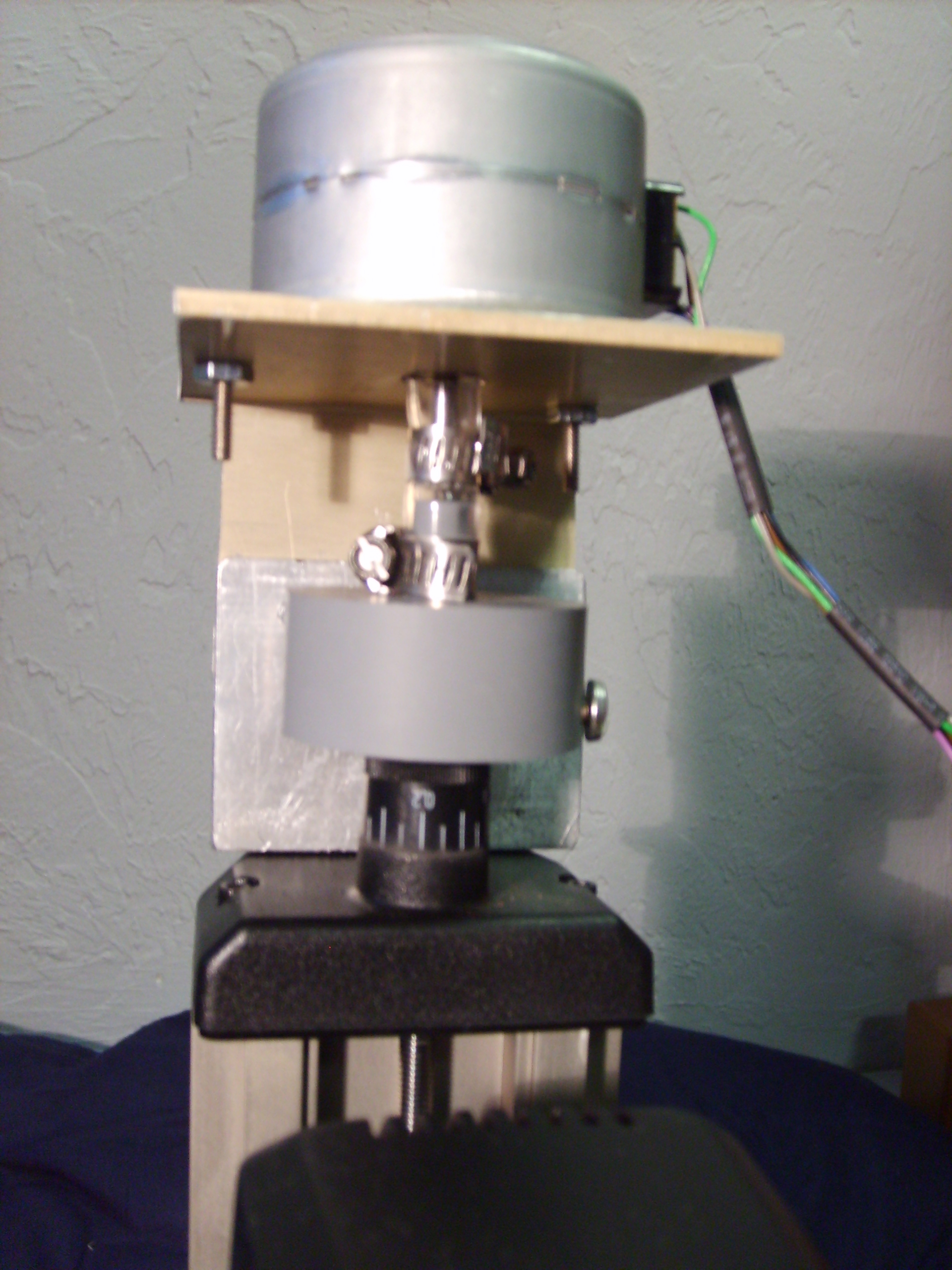
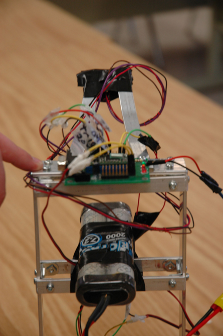
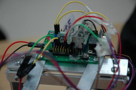
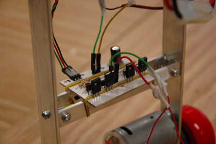
This new bot has been designed completly in aluminum. (And crafted with nothing more than a jigsaw and a drill, plus some Erector set peices.) Yet still, it’s nicer than the previous models. It balanced nicely, has a large electric drill motor and sonar.
I am yet to have it balance indefinatly, at which point I will write a whole paper about doing this. However right now, I will just list the various versions, and how well they worked.
Version 1


This was (obviously) the first version. It was about 4 feet tall. I found that my motors move way too slowly to keep a bot this size up. Thus we went to the next version.
Version 2
I chopped off about a foot and a half, so the bot is now 2 and a half feet. I figured that the bot would be able to right itself better since the moment arm is shorter, thus the same linear speed is a much faster angular speed. It now stands for about 10 seconds, but inevitably still falls.
Version 2.5
I found that the problems were due to inaccurate readings in the IR sensors. So I made a running array of the last 8 values, and used the average of them for the calulation. This didn’t quite work, either. Look at these graphs:
For both of these tests, the IR sensor was stationary in a vise pointed at a wall. That should give you some idead how inaccurate it is. The first is without my fix:
And with the fix:
Version 3
I gave up on the IR sensors: now I’m using sonar. It’s much more accurate, but I only have one. So the bot now balances for about 20 seconds, but the wheels simply can’t go fast enough to catch up if it gets moving more than a few inches per second. I hope to make some new wheels today.
Version 3.1
I ran over to the wood shop (we don’t have a metal shop) and made some bigger wheels… it seemed to me that the servos had quite a bit of torque, but didn’t go fast enough. Thus, increase the radius, we increase the distance traveled per revolution.
Version 4.0
The whole bot has been completly redesigned. The wheels of wood were not prefectly true, and thus wobbled way too much to balance properly. Also, the body was not ideal, the motors weren’t good enough, it was too tall, heavy in the wrong places….
This new bot has been designed completly in aluminum. (And crafted with nothing more than a jigsaw and a drill, plus some Erector set peices.) Yet still, it’s nicer than the previous models. It balanced nicely, has a large electric drill motor and sonar.
Email me:
jack {@} crepinc.com
Recent Projects:
Analog HF Transmitter
Audi ECU Reverse Engineering
Dual DAC QAM Modulator
FPGA QAM Modulator
Geiger Counter
Gyro-Stabilized DSLR Platform
Hybrid Rocket Engines
Turbocharger Controller
WWVB Rx and Tx
Older Projects:
Balancing Bot
Capacitor Array
CNC Mill
DCIR Renderer
Electric Gokart
Hovercraft
Low Alt. Temp. Model
Shopping Cart Locker
Trebuchet
My Twitter occasionally shows projects I'm working on.
My GitHub has code from a few projects on it.