Wednesday, May 28. 2008
Closer to leaving the ground...
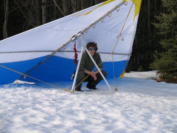
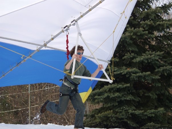
Tried really hard today, but never made it off the ground.
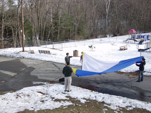
Today I did a lot of math regarding the lift of a non-airfoil wing. From the math and review of the videos, my best bet is that we aren’t properly maintaining the right angle of attack during takeoff. The leading edges aren’t near strong enough either, but that’s something I can’t fix (if anyone knows where to get thin wall aluminium tubes I would love to purchase two…)
In any case, I will be in NJ at the end of this week. I have a couple ideas as to increasing the angle of attack. I’ll be sure to post pics, and with any luck video of some flight!
Sunday, February 17. 2008
Radios Radios Everywhere
Thursday, January 24. 2008
Talking to Space
In an effort to promote radio and space to other WPI students and staff, Theo, KC2RMJ and I (KB1OZL, now NA1C) put together an event with WPI Wireless to talk to the International Space Station during a particularly good pass last November. I found the pictures of the event and thought they were nice.

I put together one of our (WPIWA’s) smaller towers for the event, and kept it outside my apartment for a few days leading up to the event. Also, I built a 2 meter J Pole antenna since it had pretty good gain at the horizon to help lengthen our window. I modified it a bit from what hams generally use (I used much larger tubing), but as I expected it made the antenna much more wideband. We got about 6 dBi, at <1.5 SWR across the band. Nice!
Unfortunatly, the ISS was speaking packet that day, and we were expecting voice. It was certainly fun to hear a space station transmitting, but it still would have been nicer to get voice.
Monday, January 14. 2008
Our network has pretty lights
Wednesday, November 14. 2007
Capacitor Array
Sunday, April 8. 2007
Current Happenings
Monday, April 2. 2007
New Z Axis Motor
Sunday, March 25. 2007
CNC Explosions and Rockets
I’ve been using the mill succesfully for a few weeks now making several PCBs. It’s really been great being able to design a board and have it in my hand within an hour. Unfortunatly, the Z-axis motor appears to have bit the dust. I came back from the other side of the shop to some bad-sounding noises, and the bit was quite embedded in the pcb… so no boards until I can take a look at that.
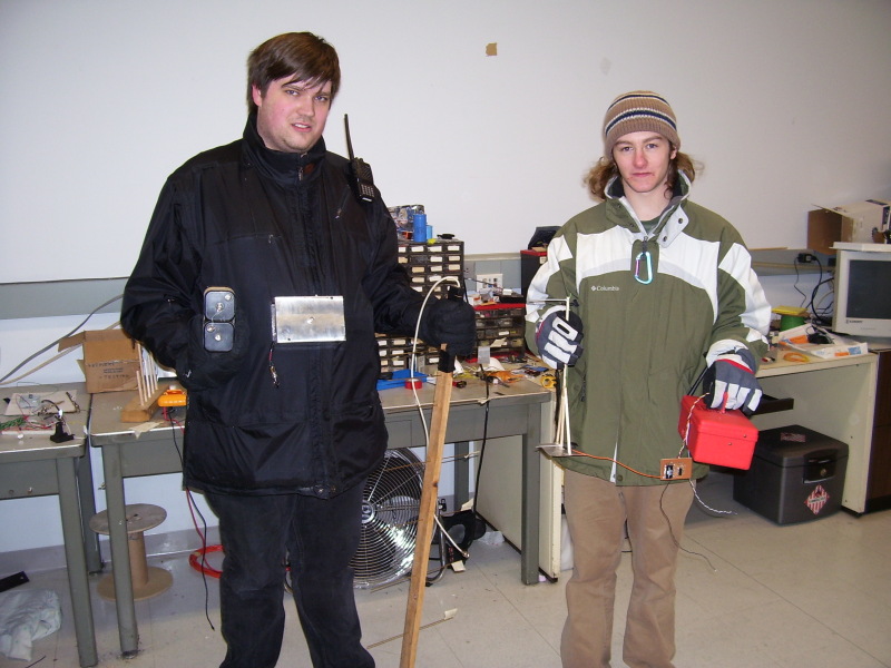
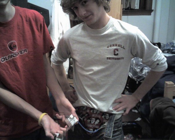
I made a few boards for my friends MQP (a kind of senior thesis project at WPI). His team is making a large rocket with an onboard computer and needed a wireless control. I designed and built him a transmitter and receiver from Lynx chips. They seem to work amazingly… more on that after the launch.
Ryan and I just after testing the range. We look oh-so-happy:
Very slow progress continues on the new 44″x22″ mill, but what little time I’m not doing school work I’m doing the rocket project. Hopefully things will clear up a bit soon.
Tuesday, January 23. 2007
CNC Machine Works!
Update 2012: I ended up purchasing real steppers so that I can actually get things done in a reasonable amount of time. After the controller I made melted again, I ended up purchasing an $80 chinese model that has been working well ever since. I have the mill at the shop and still use it to make parts for work. That said, this was the FIRST thing I ever machined myself, so yes, it looks horrible. It does work though.
I’ve wanted to build a CNC machine for about 2 years now (since I found out what one was). Mostly I wanted one to make robot parts and such, since I always had problems machining them by hand. This year I finally had the tools available to me to fabricate the parts neccesary to convert a standard mill to CNC. I got a wicked small Proxxon MF-70 for christmas (thanks parents!), and went about the process.
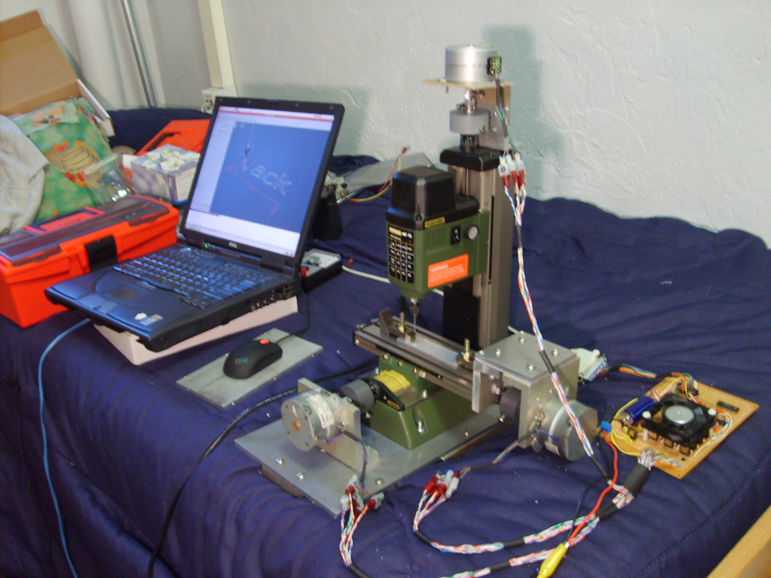
My friend Ken had 3 matched unipolar stepper motors from Cannon scanners that he donated to the cause (to be fair, I agreed to make him PCBs with the mill). I first built a controller that converts steps and direction signals from the parallel port to stepper control signals. First, the direction and step signals are converted to the correct stepper high and low states for the stepper motors by 3 L297 chips from ST Micro. I really do love these drivers, and use them in pretty much any project involving a stepper. Since the logic of these chips can’t sink or source 3 amps, I use 12 TIP102 transistors (4 per motor, 1 per coil wire) to provide switching to the motors. Each motors’ common line is hooked to the +12v supply from the board, and each control line is ground-side switched by the transistor.
The only other things on the board are a giant filter capacitor (stepper motors are very spiky things), a 5v regulator, a P3 fan to cool the transistors, and some pretty LEDs to a) let me see which liens are changing in order to debug things and b) look cool. (Click on any picture for a larger view)
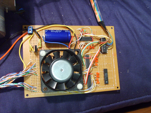
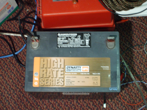
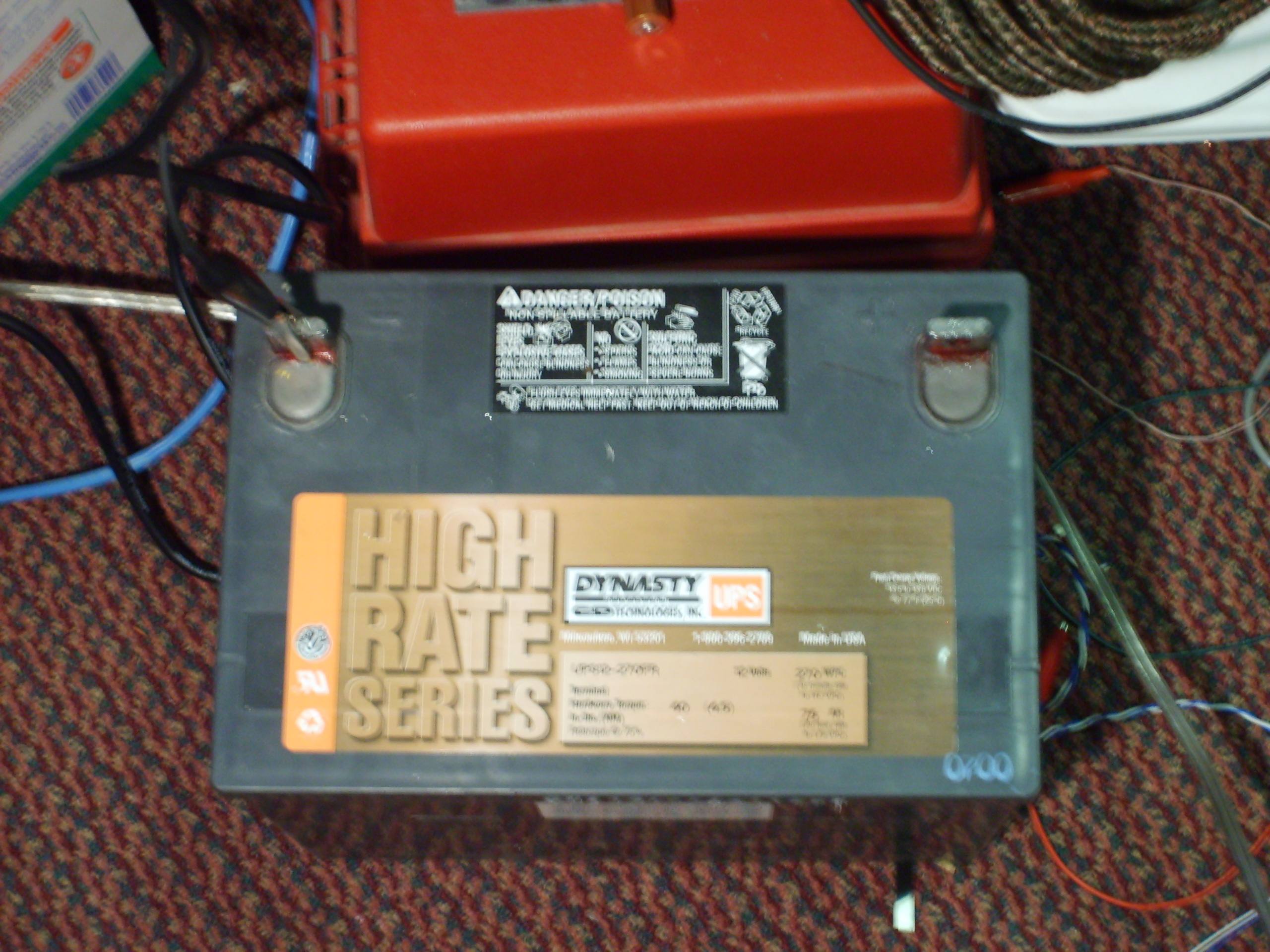
The whole unit is currently powered by a giant 12v lead acid battery. I guess I’ll eventually have to find a way to charge this thing or build a power supply, but I had this sitting around and didn’t feel like making a supply. I’ve used the mill quite a bit so far and it hasn’t noticably discharged. Update 2012: Still using that lead acid
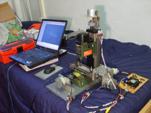
So… here it is And yes, that is my bed. Note that a CNC mill in your bed makes it not very condusive to sleeping… but some things can be sacrificed.
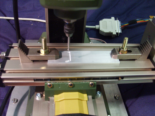
Close up of the front: (Yes, that's a ball tool for a dremel.. don't worry I did eventually learn how to machine things properly)
The X-axis controller:

Y-axis:
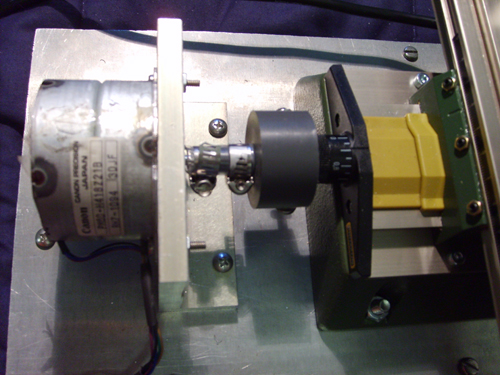
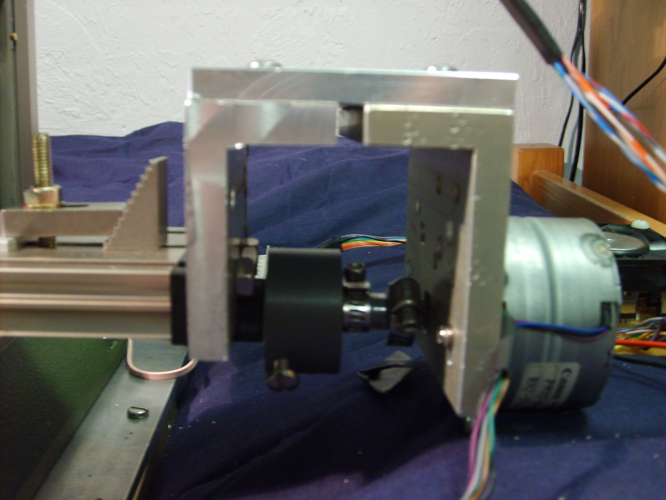
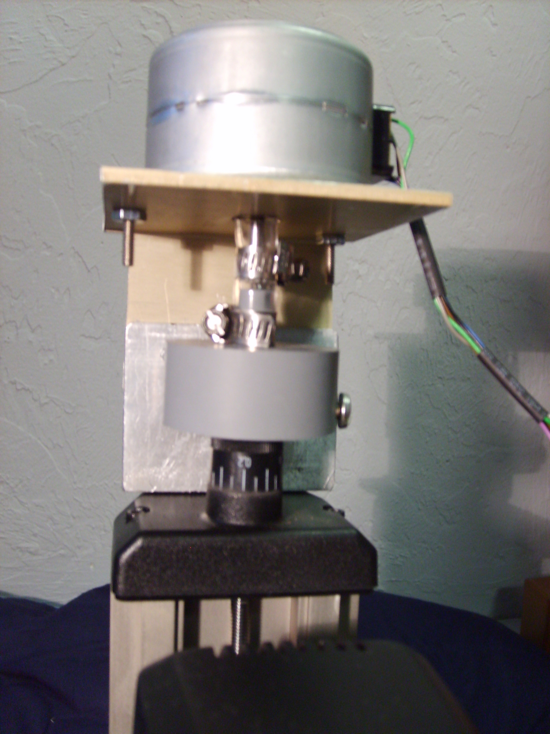
Z-axis:

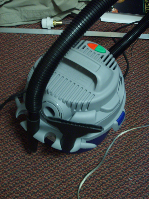
I got this sweet 2.5 horsepower 2.5 gallon shop vac. It fits right next to the spindle and moves up and down with it, so it sucks up all the aluminium, as well as cools the bit fairly well. It effectively keep aluminium off of my bed.
This is really the best thing I’ve made so far, but I hope to get time to work on some cooler projects shortly in the future.

I’ve wanted to build a CNC machine for about 2 years now (since I found out what one was). Mostly I wanted one to make robot parts and such, since I always had problems machining them by hand. This year I finally had the tools available to me to fabricate the parts neccesary to convert a standard mill to CNC. I got a wicked small Proxxon MF-70 for christmas (thanks parents!), and went about the process.
My friend Ken had 3 matched unipolar stepper motors from Cannon scanners that he donated to the cause (to be fair, I agreed to make him PCBs with the mill). I first built a controller that converts steps and direction signals from the parallel port to stepper control signals. First, the direction and step signals are converted to the correct stepper high and low states for the stepper motors by 3 L297 chips from ST Micro. I really do love these drivers, and use them in pretty much any project involving a stepper. Since the logic of these chips can’t sink or source 3 amps, I use 12 TIP102 transistors (4 per motor, 1 per coil wire) to provide switching to the motors. Each motors’ common line is hooked to the +12v supply from the board, and each control line is ground-side switched by the transistor.
The only other things on the board are a giant filter capacitor (stepper motors are very spiky things), a 5v regulator, a P3 fan to cool the transistors, and some pretty LEDs to a) let me see which liens are changing in order to debug things and b) look cool. (Click on any picture for a larger view)

The whole unit is currently powered by a giant 12v lead acid battery. I guess I’ll eventually have to find a way to charge this thing or build a power supply, but I had this sitting around and didn’t feel like making a supply. I’ve used the mill quite a bit so far and it hasn’t noticably discharged. Update 2012: Still using that lead acid
So… here it is And yes, that is my bed. Note that a CNC mill in your bed makes it not very condusive to sleeping… but some things can be sacrificed.

Close up of the front: (Yes, that's a ball tool for a dremel.. don't worry I did eventually learn how to machine things properly)
The X-axis controller:
Y-axis:

Z-axis:
I got this sweet 2.5 horsepower 2.5 gallon shop vac. It fits right next to the spindle and moves up and down with it, so it sucks up all the aluminium, as well as cools the bit fairly well. It effectively keep aluminium off of my bed.
This is really the best thing I’ve made so far, but I hope to get time to work on some cooler projects shortly in the future.
Tuesday, November 28. 2006
H4x0ring Price Chopper
Forewarning: I may or may not have participated in any of the events listed herein. This may be pure fiction, take from it what you will. That said, it was pretty awsome…
If you’ve ever been to a supermarket in a city (like Worcester), you’ll have likely noticed a locking mechanism on one of the front wheels. It’s designed to lock the cart so that it won’t roll when you try to take it off the lot, so that people don’t steal them.
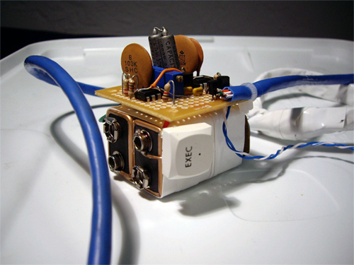
Around the perimeter of the parking lot, there is a wire acting as an antenna, transmitting an 8 khz square wave gated at 30 ms. This is the locking function. Using two LM555 timers, a few capacitors and resistors, and a coil of wire, a friend and I made our own transmitter.
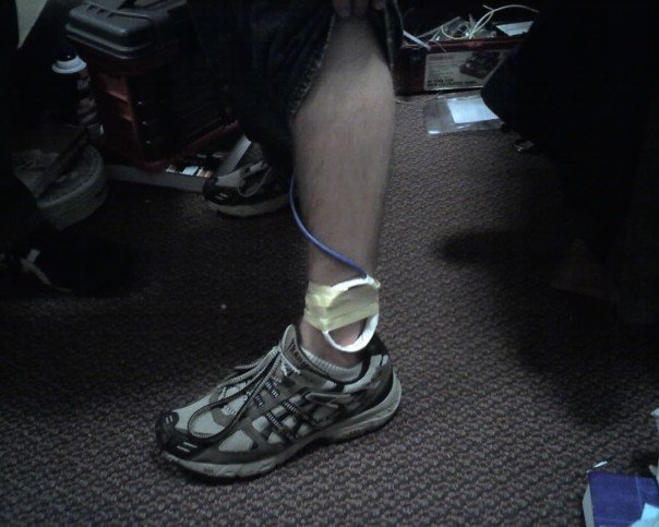
The transmitter was in my pocket with two switches: to select between lock and unlock, and to active the coil. Since the coil was down at my ancle, this waranted a wire up my pants.
We headed down to the supermarket in the middle of the night, and walked past a line of carts outside: click click click click click click click. They were all locked. The transmitter worked the first time.
We went inside and locked a few carts while they were moving as well, which obivously confused the people moving them.
If you’ve ever been to a supermarket in a city, you’ll have likely seen a lock on one of the front wheels of the carts to prevent people from stealing them. A friend and I managed to make a transmitter so that we could the carts would lock when I walked by with the transmitter in my pants.
If you’ve ever been to a supermarket in a city (like Worcester), you’ll have likely noticed a locking mechanism on one of the front wheels. It’s designed to lock the cart so that it won’t roll when you try to take it off the lot, so that people don’t steal them.
Around the perimeter of the parking lot, there is a wire acting as an antenna, transmitting an 8 khz square wave gated at 30 ms. This is the locking function. Using two LM555 timers, a few capacitors and resistors, and a coil of wire, a friend and I made our own transmitter.
The transmitter was in my pocket with two switches: to select between lock and unlock, and to active the coil. Since the coil was down at my ancle, this waranted a wire up my pants.
We headed down to the supermarket in the middle of the night, and walked past a line of carts outside: click click click click click click click. They were all locked. The transmitter worked the first time.
We went inside and locked a few carts while they were moving as well, which obivously confused the people moving them.
If you’ve ever been to a supermarket in a city, you’ll have likely seen a lock on one of the front wheels of the carts to prevent people from stealing them. A friend and I managed to make a transmitter so that we could the carts would lock when I walked by with the transmitter in my pants.
Friday, November 24. 2006
MIT Splash '06
Saturday, October 7. 2006
Neural Nets, Genetic Algorithms, and Cellular Automata
I read a book about biological computing recently, which got me interested in neural nets, genetic algorithms, and cellular automata. Perhaps I'll write up some science about each of them soon, but for now here are a few test codes I wrote to play with this stuff.
cells.c: A quick cellular automata simulation to play with different edge conditions and such. The linked version has my setup that allows a colony to continue living:
neural-backprop_g.c: Flat neural net model with back propagation. The important stuff is in main() if you want to play with it. I plan to write a proper library with this soon, so look for that.
Thursday, April 27. 2006
Electric Gokart
Update: Now that I actually know how to machine things, I’m going to revamp the Kart next time I’m home. Real bearings for the steering assembly, pedals and a floorboard, etc. Should be interesting…
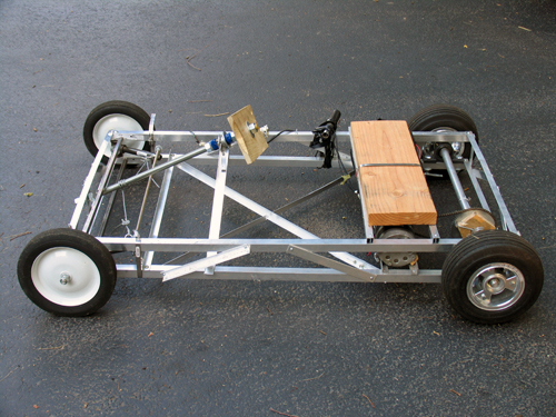
I built this “Kart” basically because I wanted to see if I was good at building large (or larger than normal) things, and to satisfy a “project” requirment for my physics class. While most people built small electronics projects on breadboards, I built this. People were pretty surprised.
Update to the update: The frame got turned into a trike for the hang glider, and the motor got imported to a scooter. Both were epic.
Frame
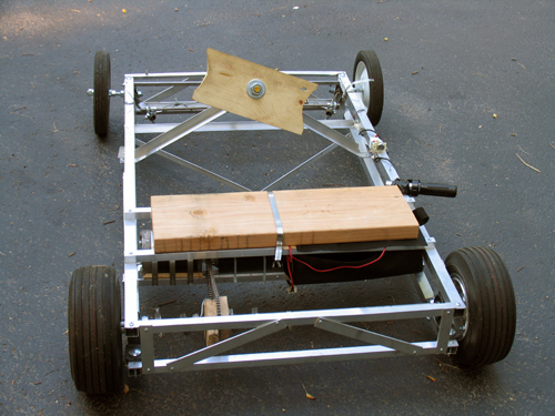
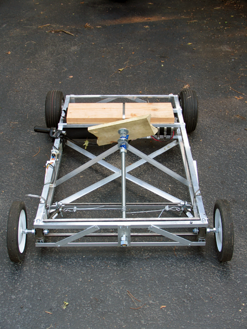
The frame was designed (in my head, since I can’t draw) to be very light, but hopefully still fairly strong. Four 1″ square aluminum stock bars run the length of the frame as 4 edges of a box. Each side of this “box” is then held the proper distance apart by perpendicular flat stock and held rigid by 2 opposite-direction diagnals of either flat stock or square stock.
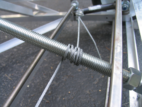
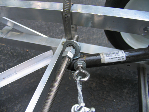
The cross peices that go between the frame sides in the front are 1/2″ inch steel square stock. It is absolutly key that these side sections stay the same distance apart, as they control the cambre of the wheels. The steel is held in place by threaded rod. (I would have used aluminum, but Home Depot is terrible at restocking and never had enough.)
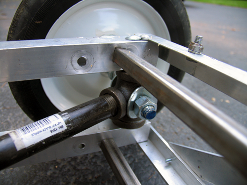
The front wheels are lame garden wheels from Home Depot (about $8 each) with built in bearings. It remains to be seen how long the bearings will last, but they haven’t fallen out yet…
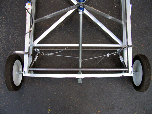
Steering
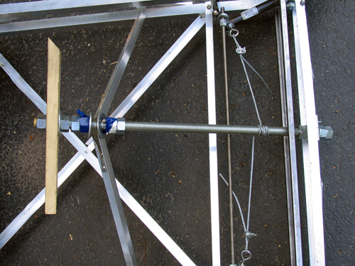
The steering idea was conceived by Sean Manix and Joe Gage in a gravity-powered car we built long ago. I modified the design somewhat to work here. Basically, the system works as a rack and pinion system does, minus the rack and the pinion. The tierod keeps outward tension on the steering arms so that they stay the proper distance apart and the wheels stay parallel; the wire pulls the whole sytem to one side or the other to steer while at the same time keeping tension on the steering arms so they stay on the tierod.
Yes, the steering arms are made of plumbing equipment.
Inside those plumbing T’s, bolts come in from both square sections of frame. Roller skate bearings (that I had around and just happened to fit) go over the bolts and space the plumbing to sit in the center. I then put the T’s on the drill press and put the 1/2″ holes in them. Let me tell you, that was scary. The bit has a tendancy to catch coming out the other side, so the whole T arm unit spins around the bit fast enough to break your arm.
As inaccurate as this looks, it actual is very smooth and tight. The steering feels nice while youre driving.
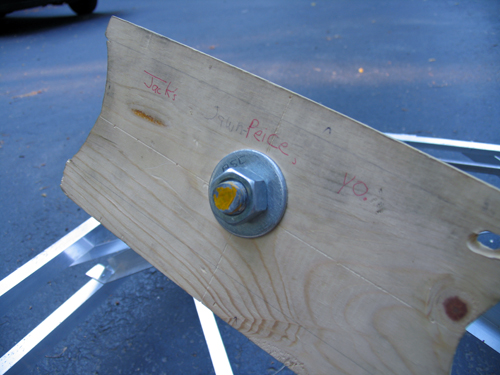
…don’t ask, it’s a school thing somebody wrote. But yes, that is the “steering plank”.
Drive Train
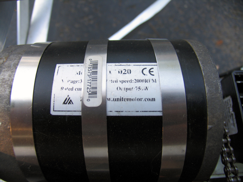
The motor is from an electric scooter. It’s 750 Watts… in pure energy, 1 horsepower = 746 Watts, but I think here the 750w describe amount of power the motor pulls from the batteries, not the mechanical energy put out. Since the motor is likely only moderatly efficient, I’d say it’s in the half-horsepower range.
My girlfriend Erica is building a kart on the same design as this one. I helped her get her motor… hers is 1200w. I think I’ll still be able to beat her once I figure out how to put some sort of transmission on this thing. The chain and rear cog are from the scooter too.
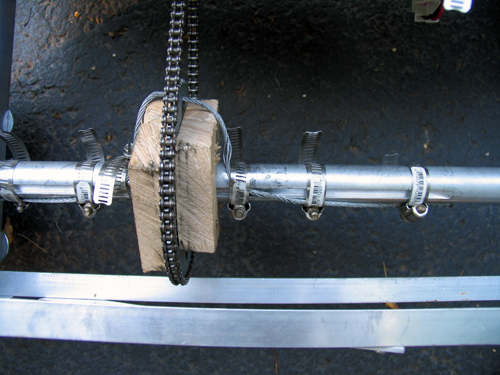
The bain of my existance… the blocks holding the rear sproket are badly made and thus wobble. The axle (1″) has a keyway in it, and the sproken has a 2″ hole. Logically, we’d make spacers to simply hold it in the center, and the spacers would fit the keyway to spin it. I built two of these out of hard wood. I cut the 1″ and keyway with a coping saw (which was a hard process), screwed the whole thing together, and slapped the chain on. It looked perfect. As soon as I touched the throttle, the keyways sheared off (wood doesn’t deal with shear stress very well) and the whole unit simply spun.
Despite efforts to make some sort of key, each time something would slip or shear off as I don't have access to any sort of metal shop. Thus, the steal cable goes through the hole in the sproket and get band clamped to the axle. The wood simply acts to keep the sproket in the right place, and the cable deals with transfering the torque to the axle. It’s ugly, and the chain pops off occasionally. I need to make some sort of mount from aluminum…
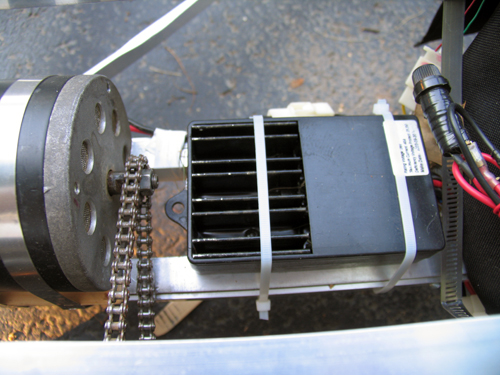
This is basically just a large version of the electronic speed controller in a remote control car. Rather than having huge variable resistors, the “ESC” as its called simply pulses the motor very quickly, and by varying how many of these pulses are “on” and “off” we vary the speed.
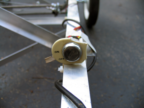
Ignition… because I can.
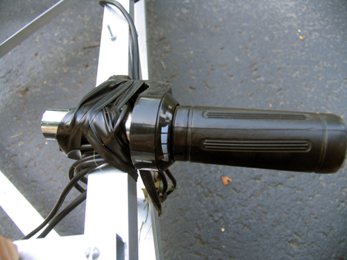
The throttle from the scooter. Yes, it is taped to the side. I haven’t had a chance to fasion some sort of pedal yet.
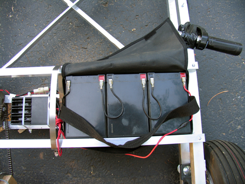
Three 7 Ah lead acid batteries power this 36v beast… they’re heavy.
Final Thoughts
In case you were wondering, there are no brakes. I haven’t gotten to that yet. But hey, when I get to the transmission and the throttle pedal, perhaps a brake might appear.
I built this “Kart” basically because I wanted to see if I was good at building large (or larger than normal) things, and to satisfy a “project” requirment for my physics class. While most people built small electronics projects on breadboards, I built this. People were pretty surprised.
Update to the update: The frame got turned into a trike for the hang glider, and the motor got imported to a scooter. Both were epic.
Frame
The frame was designed (in my head, since I can’t draw) to be very light, but hopefully still fairly strong. Four 1″ square aluminum stock bars run the length of the frame as 4 edges of a box. Each side of this “box” is then held the proper distance apart by perpendicular flat stock and held rigid by 2 opposite-direction diagnals of either flat stock or square stock.
The cross peices that go between the frame sides in the front are 1/2″ inch steel square stock. It is absolutly key that these side sections stay the same distance apart, as they control the cambre of the wheels. The steel is held in place by threaded rod. (I would have used aluminum, but Home Depot is terrible at restocking and never had enough.)
The front wheels are lame garden wheels from Home Depot (about $8 each) with built in bearings. It remains to be seen how long the bearings will last, but they haven’t fallen out yet…
Steering
The steering idea was conceived by Sean Manix and Joe Gage in a gravity-powered car we built long ago. I modified the design somewhat to work here. Basically, the system works as a rack and pinion system does, minus the rack and the pinion. The tierod keeps outward tension on the steering arms so that they stay the proper distance apart and the wheels stay parallel; the wire pulls the whole sytem to one side or the other to steer while at the same time keeping tension on the steering arms so they stay on the tierod.
Yes, the steering arms are made of plumbing equipment.
Inside those plumbing T’s, bolts come in from both square sections of frame. Roller skate bearings (that I had around and just happened to fit) go over the bolts and space the plumbing to sit in the center. I then put the T’s on the drill press and put the 1/2″ holes in them. Let me tell you, that was scary. The bit has a tendancy to catch coming out the other side, so the whole T arm unit spins around the bit fast enough to break your arm.
As inaccurate as this looks, it actual is very smooth and tight. The steering feels nice while youre driving.
…don’t ask, it’s a school thing somebody wrote. But yes, that is the “steering plank”.
Drive Train
The motor is from an electric scooter. It’s 750 Watts… in pure energy, 1 horsepower = 746 Watts, but I think here the 750w describe amount of power the motor pulls from the batteries, not the mechanical energy put out. Since the motor is likely only moderatly efficient, I’d say it’s in the half-horsepower range.
My girlfriend Erica is building a kart on the same design as this one. I helped her get her motor… hers is 1200w. I think I’ll still be able to beat her once I figure out how to put some sort of transmission on this thing. The chain and rear cog are from the scooter too.
The bain of my existance… the blocks holding the rear sproket are badly made and thus wobble. The axle (1″) has a keyway in it, and the sproken has a 2″ hole. Logically, we’d make spacers to simply hold it in the center, and the spacers would fit the keyway to spin it. I built two of these out of hard wood. I cut the 1″ and keyway with a coping saw (which was a hard process), screwed the whole thing together, and slapped the chain on. It looked perfect. As soon as I touched the throttle, the keyways sheared off (wood doesn’t deal with shear stress very well) and the whole unit simply spun.
Despite efforts to make some sort of key, each time something would slip or shear off as I don't have access to any sort of metal shop. Thus, the steal cable goes through the hole in the sproket and get band clamped to the axle. The wood simply acts to keep the sproket in the right place, and the cable deals with transfering the torque to the axle. It’s ugly, and the chain pops off occasionally. I need to make some sort of mount from aluminum…
This is basically just a large version of the electronic speed controller in a remote control car. Rather than having huge variable resistors, the “ESC” as its called simply pulses the motor very quickly, and by varying how many of these pulses are “on” and “off” we vary the speed.
Ignition… because I can.
The throttle from the scooter. Yes, it is taped to the side. I haven’t had a chance to fasion some sort of pedal yet.
Three 7 Ah lead acid batteries power this 36v beast… they’re heavy.
Final Thoughts
In case you were wondering, there are no brakes. I haven’t gotten to that yet. But hey, when I get to the transmission and the throttle pedal, perhaps a brake might appear.
Monday, February 13. 2006
DCIR Renderer
Many people can go on and on about the “beauty of math”: everything fits, and that’s amazing. Personally, I think math is pretty handy, but not always that pretty. But hey, I suppose I proved myself wrong in this latest project.
DCIR is a program that renders pretty pictures based on a chaotic set of functions- the DeJong equations:
You can get the source here: single machine (dcir.c), distributed (dcir_d.c)
While this method is great, it’s outrageously slow. Thus, the name suggests, DCIR is going to be “distributed”, or cluster-ready. At the moment the single-cpu code works great, but the MPI version leaves something to be desired… It sucks about 80 Mb/s of bandwidth, then dies. (Hey, it LOOKS like it should work )
I would like to thank the developers of Fyre. Fyre is basically a better version of what I’ve made. We discussed originally how they had things set up, particularly how their clustering worked. Their version included some nice editing tools that DCIR doesn’t, as well as a built in visualizer, and an animation option. The reason I wrote my own was more of a personal challenge than a real reason, though it will be nice to have a version that runs on MPI, as opposed to running the Fyre rendering server on all the nodes of the cluster.
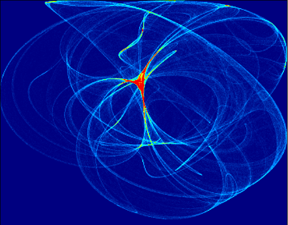
For reference, here are some old images from the first version of DCIR, as well as some nice example I’ve made with Fyre (the antialiasing sure is nice):
Trial 1 at different exposures:
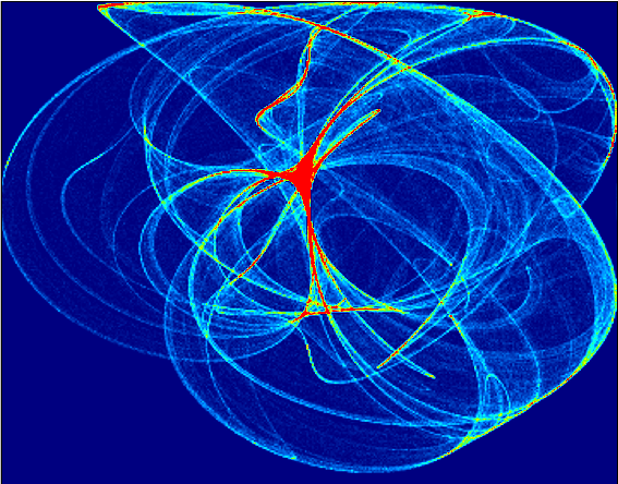
Trial 2:


Fyre:


DCIR is a program that renders pretty pictures based on a chaotic set of functions- the DeJong equations:
x' = sin(ay) - cos(bx)Thus, starting with a random a,b,c,d,x, and y, we recursivly solve for an X’ and Y’ pair, then plug them back in while keeping a,b,c, and d constant. As opposed to your average function, such as f(x) = sin(x), these functions put out chaotic numbers. That is, they don’t follw any specific method, they simply hop around. But it turns out, they tend to hop into some areas more often than others. If you take a look at the images below, you’ll see what I mean. The brighter an area is, the more times an iteration “hopped” into that area. (Clicking on a picture will make it bigger, visualizations performed using Winfeild by Andrei Chernousov)
y' = sin(cx) - cos(dy)
You can get the source here: single machine (dcir.c), distributed (dcir_d.c)
While this method is great, it’s outrageously slow. Thus, the name suggests, DCIR is going to be “distributed”, or cluster-ready. At the moment the single-cpu code works great, but the MPI version leaves something to be desired… It sucks about 80 Mb/s of bandwidth, then dies. (Hey, it LOOKS like it should work )
I would like to thank the developers of Fyre. Fyre is basically a better version of what I’ve made. We discussed originally how they had things set up, particularly how their clustering worked. Their version included some nice editing tools that DCIR doesn’t, as well as a built in visualizer, and an animation option. The reason I wrote my own was more of a personal challenge than a real reason, though it will be nice to have a version that runs on MPI, as opposed to running the Fyre rendering server on all the nodes of the cluster.
For reference, here are some old images from the first version of DCIR, as well as some nice example I’ve made with Fyre (the antialiasing sure is nice):
Trial 1 at different exposures:
Trial 2:


Fyre:
Sunday, December 18. 2005
Low Altitude Temperature Profile
This project is to make a mathematical model of the temperature at low altitudes, and how it changes as the sun warms the earth. I’m basing the model around the one dimensional heat equation. Here's the output from the model with cold boundaries and a hot initial center, linearly distributed along the left wall (time is to the right):
The actual writing of the model was about as exciting as coding usually is… pretty boring to hear about. Thus, I’ll describe that process and how it works when I get a little more time, but at the moment here are the stories of testing the model using the rockets.
I started with 2 rockets, I currently have none. Thursday we went out and launched the first rocket without the computer in it to make sure it went where we wanted. It didn’t. In the past I’d used rockets with 4 motors and two stages, but separated, on either side of the body. As you can see here, this was not the case on the test rocket:
Here the bottom two motors were taped together… this turned out to be a bad idea. Apperently the motors do not burn at the same rate exactly, so when one finished and ignited its other stage, it was cast off… while still being attached to the other. Thus the bottom motor ripped off before it had lit its upper stage, leaving the rocket underpowered. Besides that, the launch rod we used in the test wasn’t nearly strong enoough, and the rocket ended up leaving the pad at about a 45-degree angle. This wasn’t so bad until the previously-explained stage switch, in which the sudden change in acceleration made the payload and thus the CG shift forward.This shifting mass caused the rocket to further rotate, and when the (single) upper stage motor fired, the rocket was pointed horizontally along the ground, about 200 feet up. The rocket continued missle-style for the last 3 seconds of the burn, then found its way into the trees at around 250 MPH. When we found it, there were peices strewn in a 25 ft radius of the actual payload.
The payload was intended to split from the body at the end of the burn. Unfourtunatly it got stuck, and the pressue inside the fusalage went instead out a different way: through the sides. So the payload came down with a section of fusalage, parachute still stuffed inside. As it went through the trees, the fins were stripped off. The wooden nose cone must have hit a tree, because I’ve never seen dents like that in such a large piece of wood…
This left us with 3 lessons to learn for the “real deal”: 1) Don’t strap the bottom stages together, 2) Make sure the payload detaches smoothly, 3) use a much stiffer launch rod. We did these things, and the first (and unfourtunatly final) launch went smoothly, though we had to knock it over about 30 degrees due to high wind. Thus the final altitude was around 2500 feet. As the rocket fell, the fusalage detached from the payload, and its wherabouts are currently unknown. However, the payload was succesfully recovered and read about 3/4 miles from the launch rod, near the intended landing spot:

Taking into account the issues the previous models had, I built a new rocket that was meant to be the final, perfect launch. This time rather than having such a wide and heavy body with a full BX24 motherboard in it, I soldered my own board, which included an FM transmitter for tracking. It was predicted to use half the engines (3 stages, no clusters) and go 120% as high.
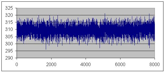
As I was testing the board I built, I noticed an issue. The temperature sensor was probed every half-second, and the radio was pulsed every second. When the two happened to coincide (a reading while the radio was transmitting), the value read by the computer was very far off. I did not originally make this connection, and thought my board was simply bad. I hooked a probe up to the positive of my battery, and poked the pin that was reading the temperature sensor. This should have returned a full HIGH value, or a 1024. Instead, the chip crashed, and never came back.
Woops… I had forgotten that the battery (9v) was going into a 5v regulator before the computer. Thus, the highest voltage expected by the chip was 5v. All the manuals with the chip indicate that reverse polarity will instantly kill a chip. When I applied the 9v, the comparator tested it against 5v, allowed current to flow backwards, and beasted the poor device.
It was 3am on launch day, and I didn’t have another chip. I decided that I might as well launch the rocket, because rockets are cool. I was rewarded with the most awesome landing yet:

Epic!
The actual writing of the model was about as exciting as coding usually is… pretty boring to hear about. Thus, I’ll describe that process and how it works when I get a little more time, but at the moment here are the stories of testing the model using the rockets.
I started with 2 rockets, I currently have none. Thursday we went out and launched the first rocket without the computer in it to make sure it went where we wanted. It didn’t. In the past I’d used rockets with 4 motors and two stages, but separated, on either side of the body. As you can see here, this was not the case on the test rocket:
Here the bottom two motors were taped together… this turned out to be a bad idea. Apperently the motors do not burn at the same rate exactly, so when one finished and ignited its other stage, it was cast off… while still being attached to the other. Thus the bottom motor ripped off before it had lit its upper stage, leaving the rocket underpowered. Besides that, the launch rod we used in the test wasn’t nearly strong enoough, and the rocket ended up leaving the pad at about a 45-degree angle. This wasn’t so bad until the previously-explained stage switch, in which the sudden change in acceleration made the payload and thus the CG shift forward.This shifting mass caused the rocket to further rotate, and when the (single) upper stage motor fired, the rocket was pointed horizontally along the ground, about 200 feet up. The rocket continued missle-style for the last 3 seconds of the burn, then found its way into the trees at around 250 MPH. When we found it, there were peices strewn in a 25 ft radius of the actual payload.
The payload was intended to split from the body at the end of the burn. Unfourtunatly it got stuck, and the pressue inside the fusalage went instead out a different way: through the sides. So the payload came down with a section of fusalage, parachute still stuffed inside. As it went through the trees, the fins were stripped off. The wooden nose cone must have hit a tree, because I’ve never seen dents like that in such a large piece of wood…
This left us with 3 lessons to learn for the “real deal”: 1) Don’t strap the bottom stages together, 2) Make sure the payload detaches smoothly, 3) use a much stiffer launch rod. We did these things, and the first (and unfourtunatly final) launch went smoothly, though we had to knock it over about 30 degrees due to high wind. Thus the final altitude was around 2500 feet. As the rocket fell, the fusalage detached from the payload, and its wherabouts are currently unknown. However, the payload was succesfully recovered and read about 3/4 miles from the launch rod, near the intended landing spot:
Taking into account the issues the previous models had, I built a new rocket that was meant to be the final, perfect launch. This time rather than having such a wide and heavy body with a full BX24 motherboard in it, I soldered my own board, which included an FM transmitter for tracking. It was predicted to use half the engines (3 stages, no clusters) and go 120% as high.
As I was testing the board I built, I noticed an issue. The temperature sensor was probed every half-second, and the radio was pulsed every second. When the two happened to coincide (a reading while the radio was transmitting), the value read by the computer was very far off. I did not originally make this connection, and thought my board was simply bad. I hooked a probe up to the positive of my battery, and poked the pin that was reading the temperature sensor. This should have returned a full HIGH value, or a 1024. Instead, the chip crashed, and never came back.
Woops… I had forgotten that the battery (9v) was going into a 5v regulator before the computer. Thus, the highest voltage expected by the chip was 5v. All the manuals with the chip indicate that reverse polarity will instantly kill a chip. When I applied the 9v, the comparator tested it against 5v, allowed current to flow backwards, and beasted the poor device.
It was 3am on launch day, and I didn’t have another chip. I decided that I might as well launch the rocket, because rockets are cool. I was rewarded with the most awesome landing yet:

Epic!
Sunday, November 27. 2005
Genetic Algorithms
Saturday, November 12. 2005
Logic Probe
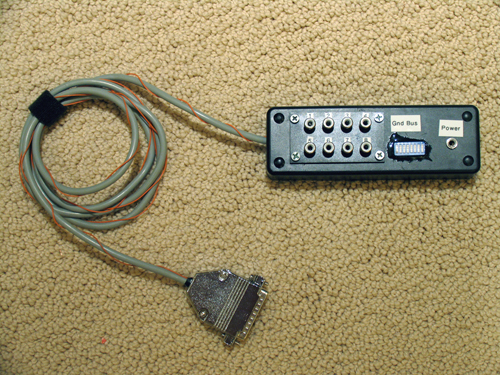
I built an interface to the parallel port for use as a logic probe. I found this program that, using its own port driver, can sample the port at up to 1MHz, on 8 channels.
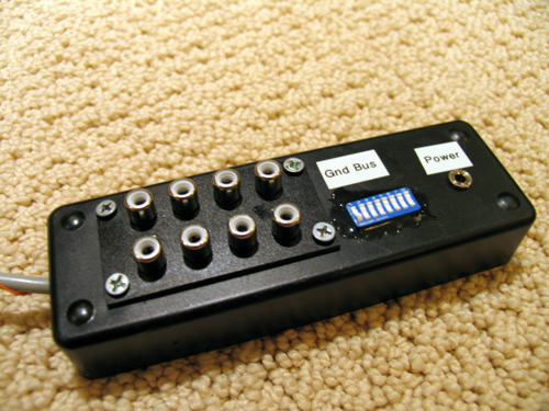
I built a pretty interface into a box with switches for the ground bus, plus I made some 2 conductor probes and some singlle conductor probes. Unfortunatly I couldn’t find any of those handy circuit clips, so I just have lame aligator clips on the probes.
While looking for something to actually do with the probe, I built a simple square wave oscillator with an LM555 timer. It was almost cool… and everything is cooler when it goes faster. So I started messing with the circuit to make it go as fast as possible. I don’t have very small capacitors, but with what I had I got the thing to 675.68 kHz. I think that’s pretty good. I poked around and got it to go a little faster, but at that point the probe began aliasing because it couldn’t sample any faster, so I couldn’t test how fast it was going.
I’m going to try to use this to reverse engeneer chips, ie monitor the memory bus and see what a particular chip is doing, but with only 8 channels and up to 1 mHz (usually about 800 kHz) it’s unlikely that I’ll find something simple enough to use it on. But hey, maybe I can still get linux on my toaster.
Wednesday, November 9. 2005
MIT Splash, Nov. 19-20. Come!
Saturday, October 29. 2005
nBody Simulations
I did a project in CS at school to simulate the movement of free bodies with gravity.

At each timestep, each body's force is evaluated with respect to every other body, vector summed, then applied. No sense writing out all the gory details here since I wrote this in a paper for class!
Here's the source, and a video clip of the simulation.
Note from 2012: don't judge my physics or writing by that PDF! Leaving it for posterity, but I've learned a bit since then...
Tuesday, October 18. 2005
The Hovercraft
A while back Mike Pontecorvo (Cornell ’09) and I built a hovercraft. It had major issues, but nonetheless could be ridden down one’s driveway.
Just recently, I decided that I needed to make a new hovercraft that had better lift and real propulsion.
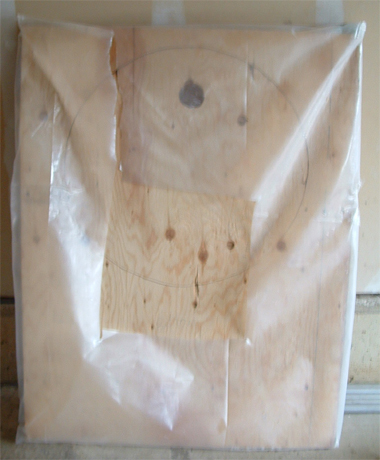
I started with a peice of 3′ x 4′ 1/2″ plywood. I cut a 24″ hole in the middle for my prop, and mounted the motor. The previous version had a leaf blower, but I figured that a prop would be better. This worked in the small test versions. Yet, after I had attached a good skirt and fired up the prop, it simply sat there, despite my prodding. I found that the model versions worked because the props spun very fast. Yet this version – a 24″ prop on a tractor starter motor – hardly acheived the same speed. Thus, my prop hoverfraft failed.
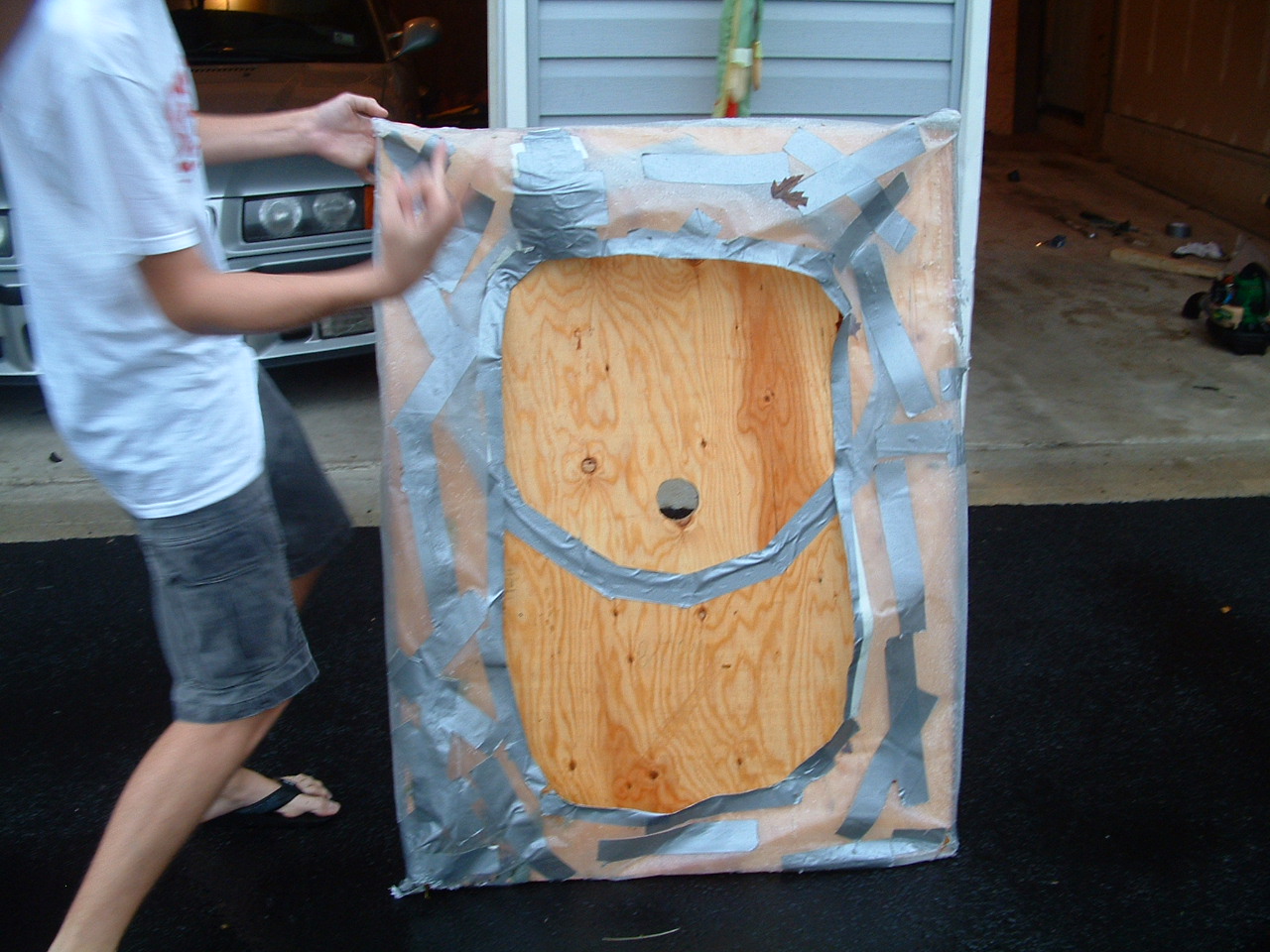
I wasn’t quite done yet though. I had designed my skirt much more efficiently than the previous version, hoping that I could use left energy for the lift fans. When I arrived at Mike’s house with this new version, we strapped on the leaf blower and gave it a run. It floated right out of the garage! Mike hopped on, and began cruising down the driveway. He probably reached 15 mph, until I heard a large POP then “Ahh!”. Apperently the un-reinforced skirt couldn’t take the pressure, and exploded.
As you can see, it ripped right up the corner. What’s was our answer to that issue, you ask? More Tape.
In the end with the tape, we took the hovercraft for a run in the pouring rain down a bit of a hill. This was quite interesting, becuase rooster tails of water and vapour came out both sides, and the ground behind was dry. But asphalt is abrasive, and we soon had more skirt holes. Perhaps this didn’t turn out to be the great project had originally hoped, but nonetheless it was quite entertaining.
Just recently, I decided that I needed to make a new hovercraft that had better lift and real propulsion.
I started with a peice of 3′ x 4′ 1/2″ plywood. I cut a 24″ hole in the middle for my prop, and mounted the motor. The previous version had a leaf blower, but I figured that a prop would be better. This worked in the small test versions. Yet, after I had attached a good skirt and fired up the prop, it simply sat there, despite my prodding. I found that the model versions worked because the props spun very fast. Yet this version – a 24″ prop on a tractor starter motor – hardly acheived the same speed. Thus, my prop hoverfraft failed.
I wasn’t quite done yet though. I had designed my skirt much more efficiently than the previous version, hoping that I could use left energy for the lift fans. When I arrived at Mike’s house with this new version, we strapped on the leaf blower and gave it a run. It floated right out of the garage! Mike hopped on, and began cruising down the driveway. He probably reached 15 mph, until I heard a large POP then “Ahh!”. Apperently the un-reinforced skirt couldn’t take the pressure, and exploded.
As you can see, it ripped right up the corner. What’s was our answer to that issue, you ask? More Tape.
In the end with the tape, we took the hovercraft for a run in the pouring rain down a bit of a hill. This was quite interesting, becuase rooster tails of water and vapour came out both sides, and the ground behind was dry. But asphalt is abrasive, and we soon had more skirt holes. Perhaps this didn’t turn out to be the great project had originally hoped, but nonetheless it was quite entertaining.
Email me:
jack {@} crepinc.com
Recent Projects:
Analog HF Transmitter
Audi ECU Reverse Engineering
Dual DAC QAM Modulator
FPGA QAM Modulator
Geiger Counter
Gyro-Stabilized DSLR Platform
Hybrid Rocket Engines
Turbocharger Controller
WWVB Rx and Tx
Older Projects:
Balancing Bot
Capacitor Array
CNC Mill
DCIR Renderer
Electric Gokart
Hovercraft
Low Alt. Temp. Model
Shopping Cart Locker
Trebuchet
My Twitter occasionally shows projects I'm working on.
My GitHub has code from a few projects on it.