Sunday, January 6. 2013
Dual DAC I+Q Generation and Carrier Modulation
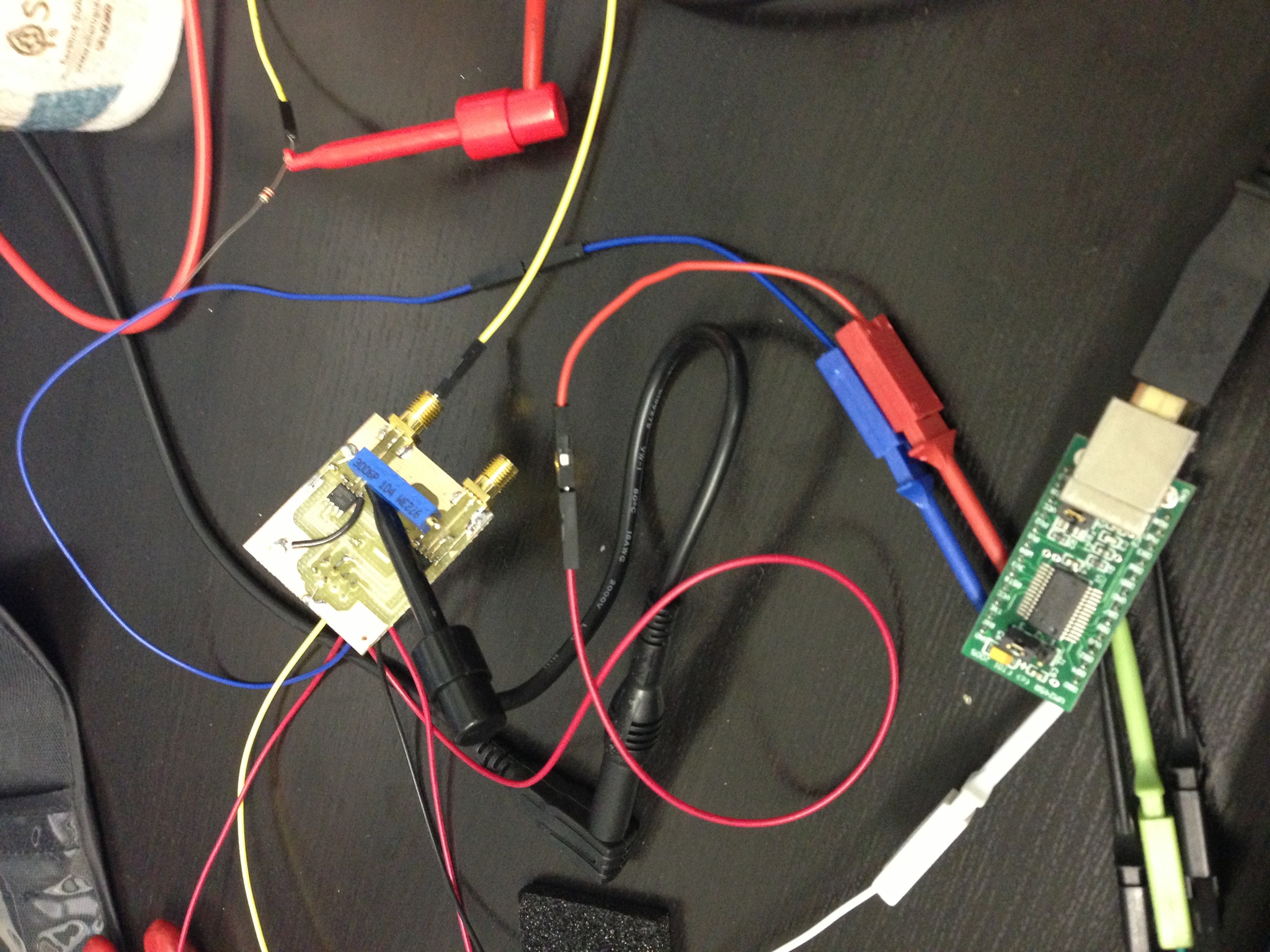
I wanted a simple, easily-interfacable QAM source to test some code I had written for the RTL-SDR, so I put together two small boards: one with two SPI DACs to generate the I and Q inputs, and one board with a single analog QAM modulator on it that takes the carrier, I, and Q signals and outputs the modulated carrier.
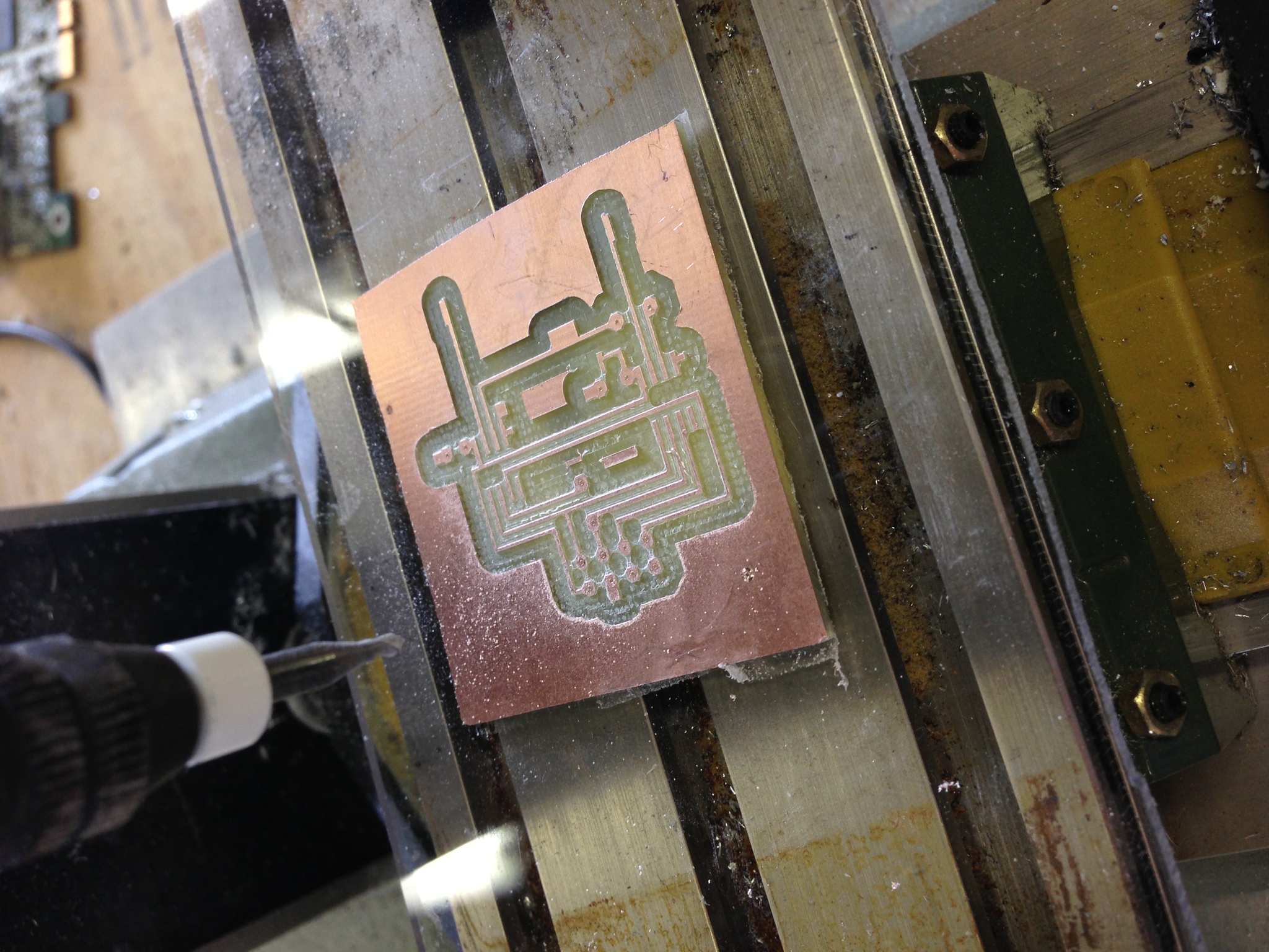
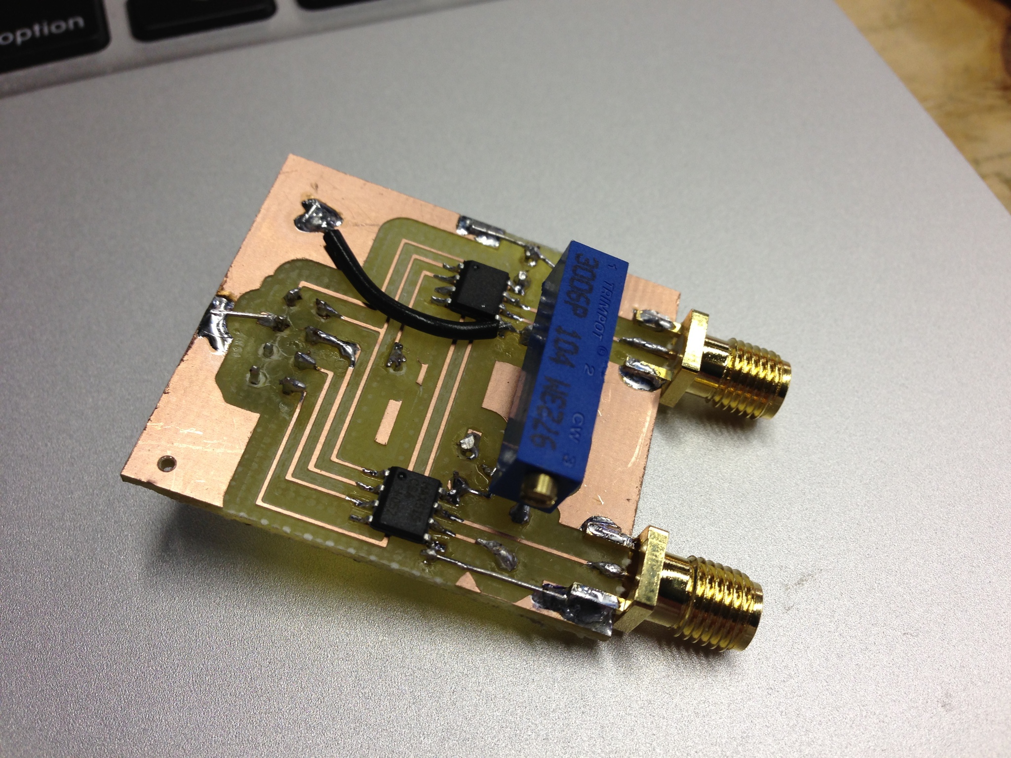
First, I made the dual DAC board with two MAX515's - simple, 10-bit, SPI DACs.
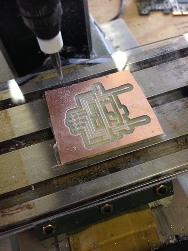
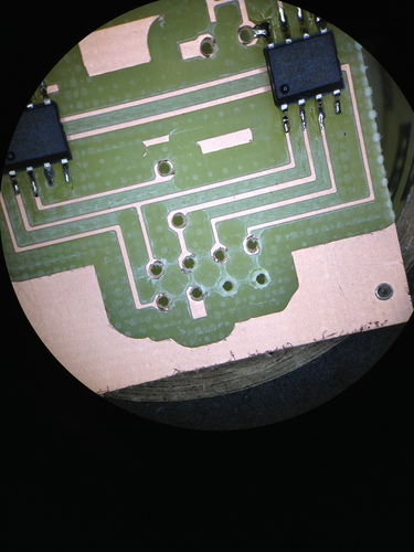
Aesthetically the board was not stunning - I used too large a drill for the through holes, and thus my pads were blown out. However, it was salavgable, so I continued putting it together and testing it by bit-banging the DACs with an FT245R dev board:
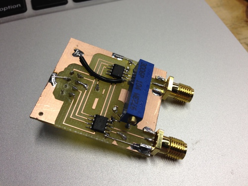
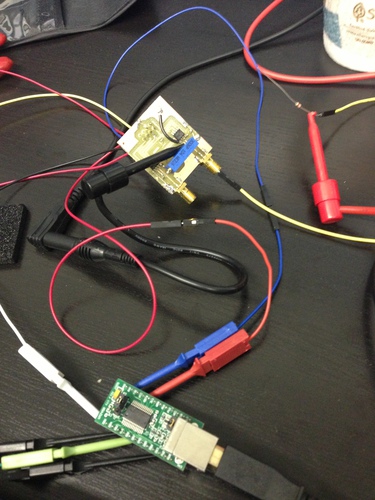
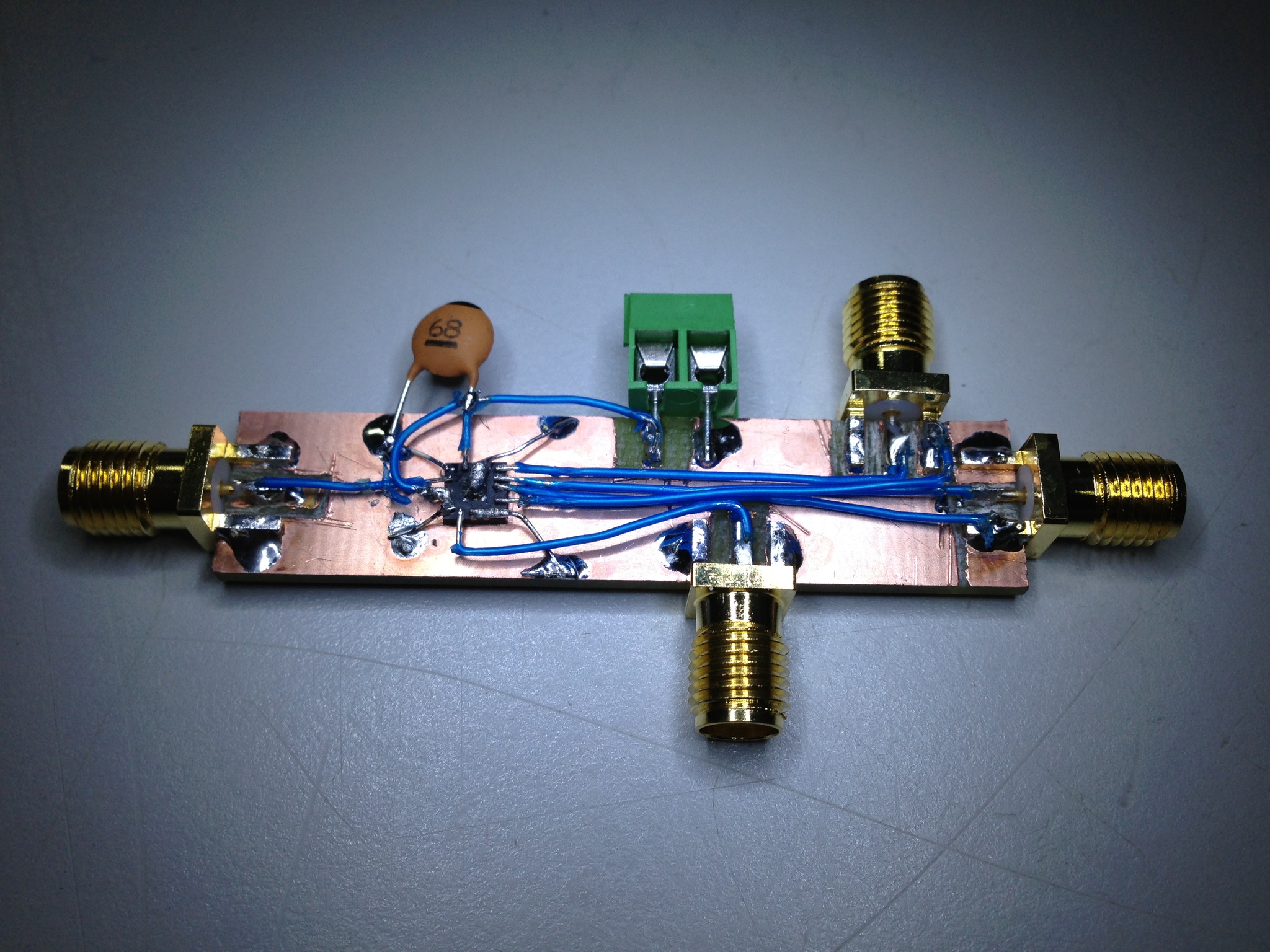
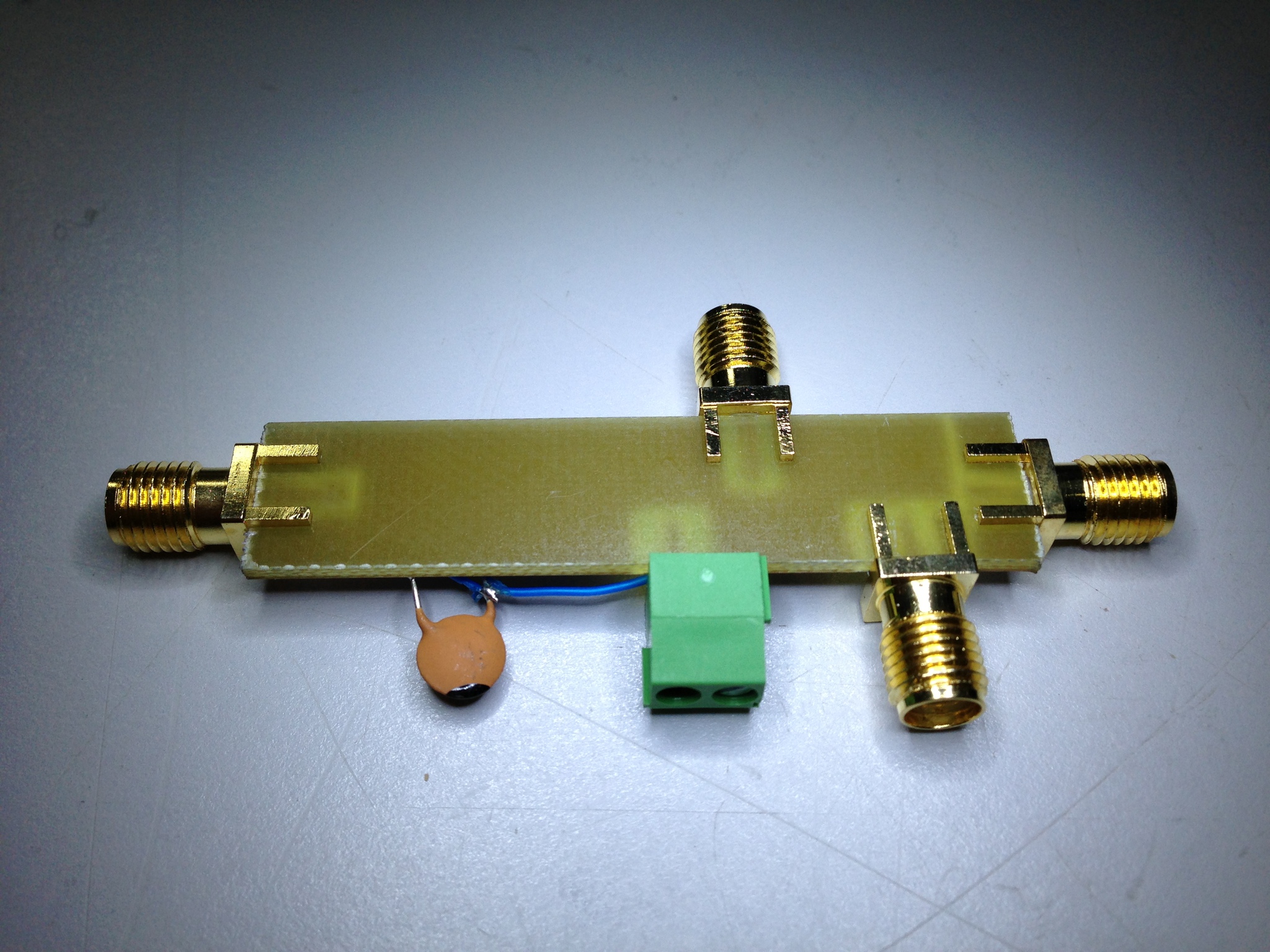
With that working well, I dead-bugged the modulator, a TRF370417 that will handle carrier freqs of 50 MHz through 6 GHz, to another board:

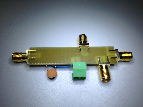
As pretty as that board turned out, it was unfortunately (and predictably) extremely noisy. Oh well, I suppose I will just have to make a proper board for all 3 chips...
First, I made the dual DAC board with two MAX515's - simple, 10-bit, SPI DACs.
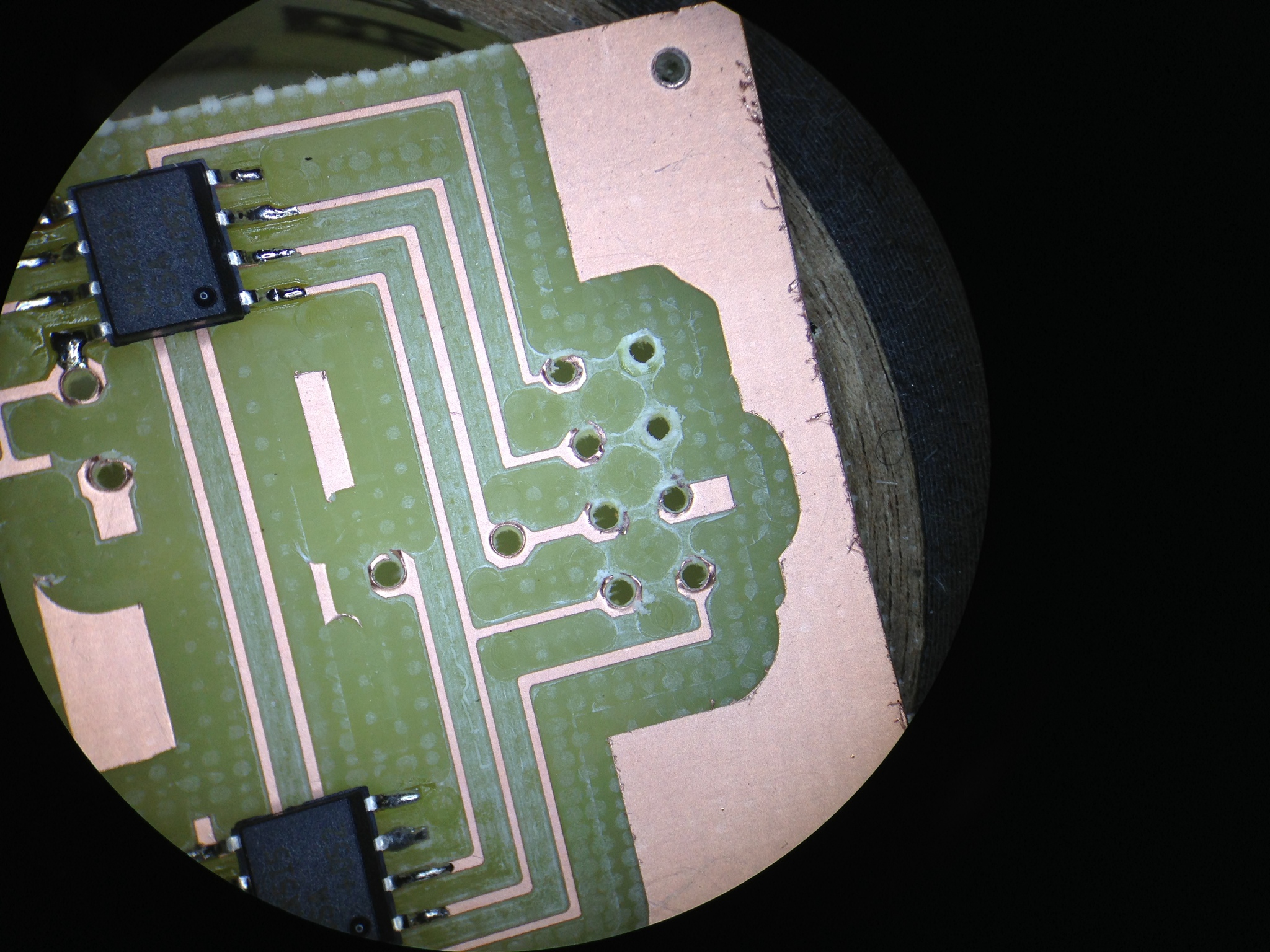
Aesthetically the board was not stunning - I used too large a drill for the through holes, and thus my pads were blown out. However, it was salavgable, so I continued putting it together and testing it by bit-banging the DACs with an FT245R dev board:
With that working well, I dead-bugged the modulator, a TRF370417 that will handle carrier freqs of 50 MHz through 6 GHz, to another board:
As pretty as that board turned out, it was unfortunately (and predictably) extremely noisy. Oh well, I suppose I will just have to make a proper board for all 3 chips...
Friday, December 21. 2012
The Earth sure is a cool place to be
Another Friday evening, flying home from work:


Saturday, December 15. 2012
Reverse Engineering an Audi ECU
The thing that annoys me most about the ECU in my car is that it gives barely any debugging information about sensors and states. It's an older car so some of the sensors started getting a little wacky, but which ones? Fast forward a week and I had decided I needed to pull the code off the ECU to see how it works, then add a few functions of my own. There are a few businesses out there that reflash ECUs for performance increases and such, so if they can do it so can I.
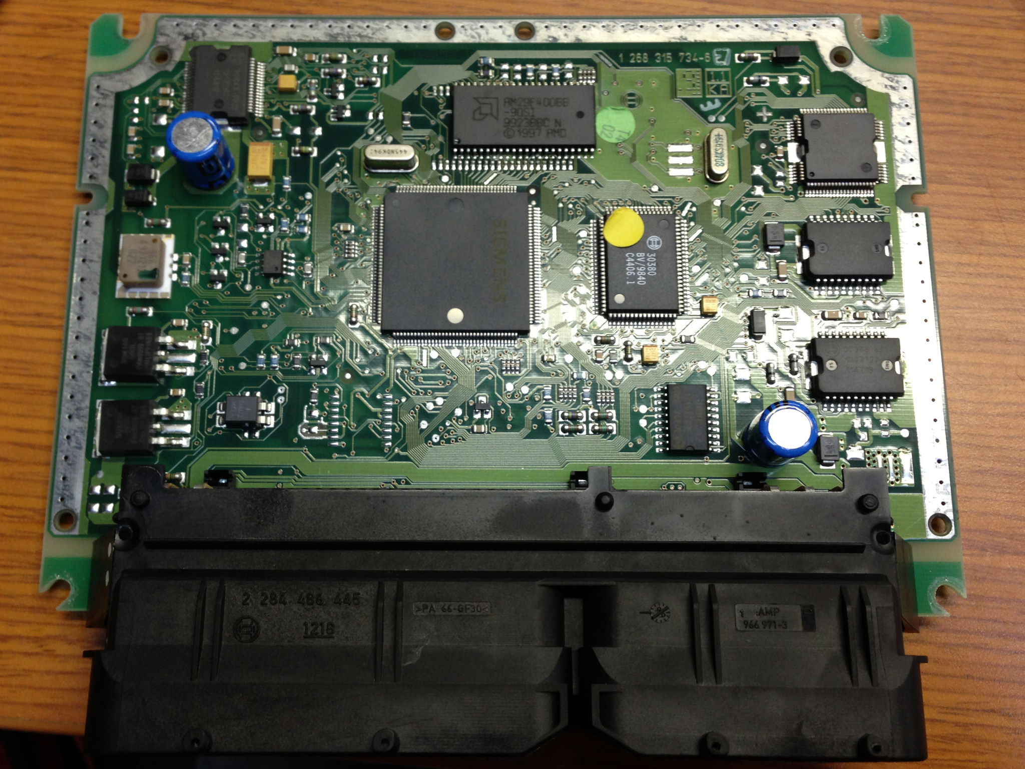
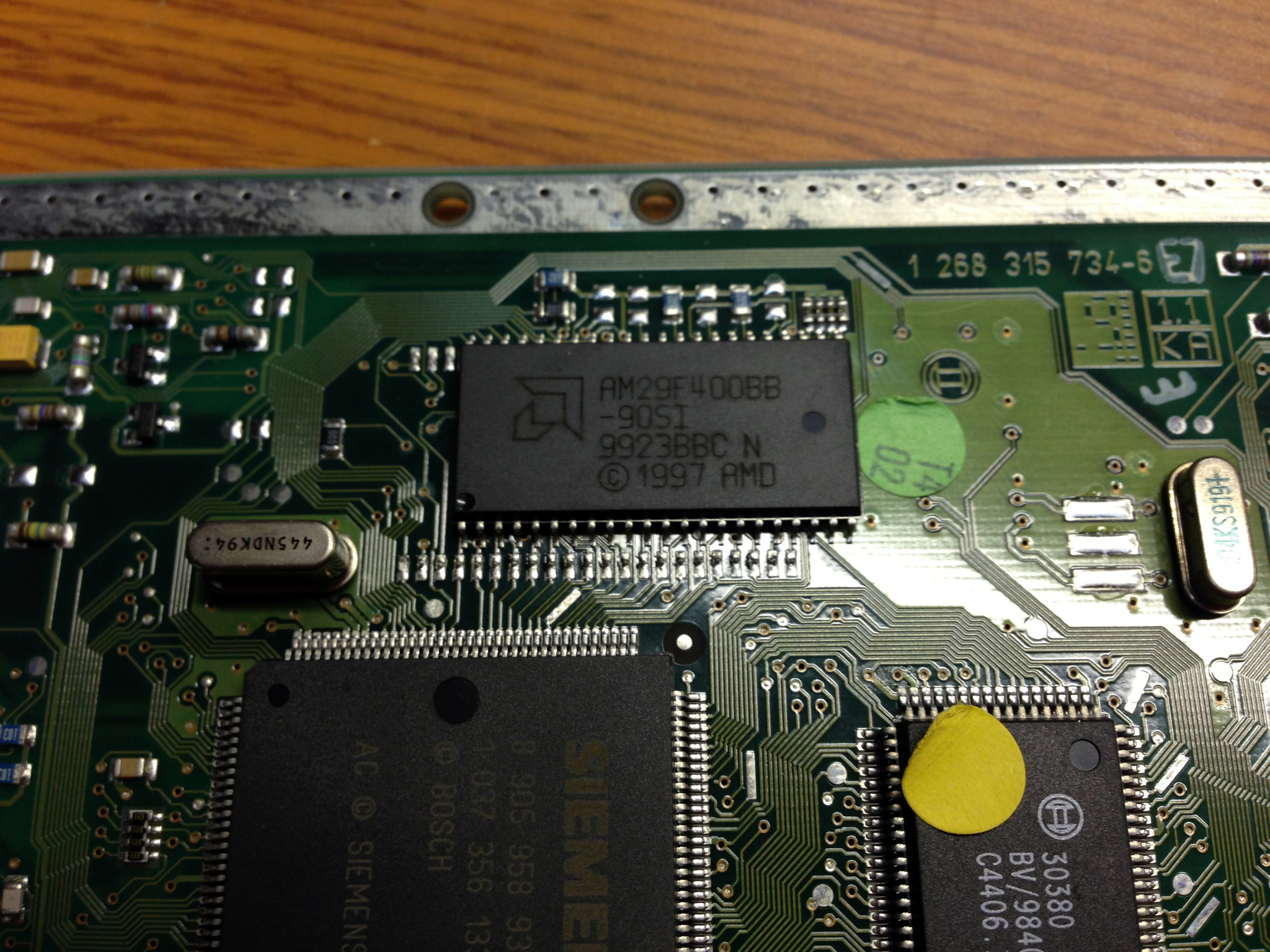
I started by grabbing an ECU for my year and model of car from a junkyard, and opening it up.

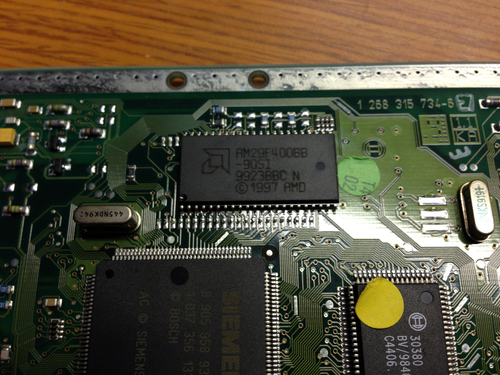
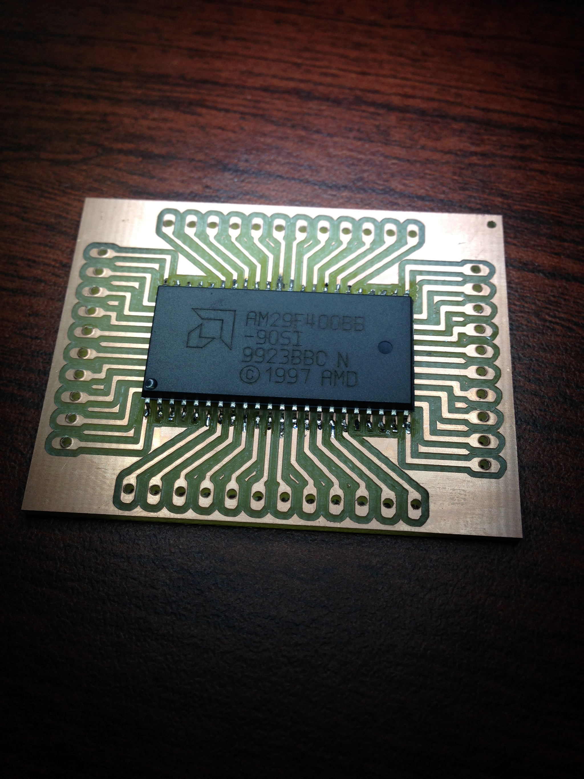
A quick glance shows that it's very simple: a C167 MCU, which loads its code from an Am29F400B flash at boot. The C167 is a great device for cars, as it has a ton of PWM channels and speaks CANBUS natively, and even includes the ability to load code via CANBUS. I was able to quickly find the datasheet and debugging hints documents, as well as a datasheet for the flash itself. Clearly, my next course of action was to yoink the flash and read it (note that in the above pics, I've already desoldered it from the board).
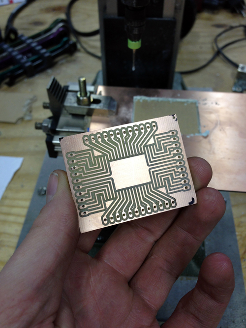
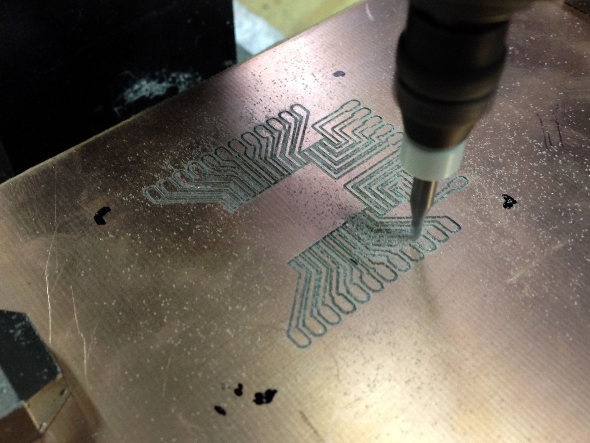
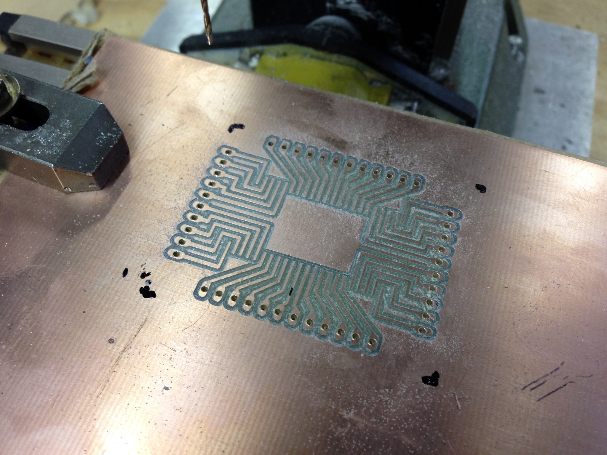
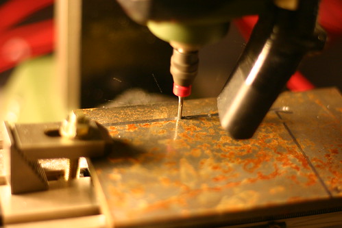
I hacked up a board design to give me easy access to the pins, and cut it using the mill:
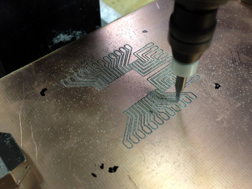

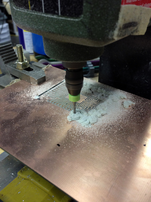
I did my math right and it came out great the first time. I had quite an internal debate about reading the data though- the elegant way to go about it would have been to write a general FPGA memory reader-writer that would also allow me to do passive memory snooping (ie, latch on address changes and record both the address and data value), but I decided to focus on one project at a time and just wrote a few lines of C for an Atmega board I had handy:

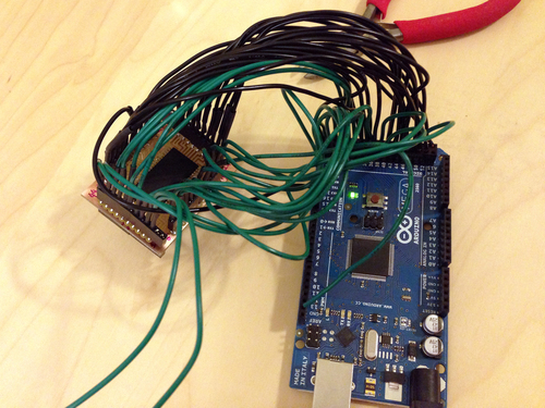
It worked nicely! I need to spend some time mapping out the IO addresses, but at first glance, the bootloader has an amusing tamper-protection scheme. The first block of code on the flash loads data into RAM from farther down the flash itself... but adds 1 to each value. Thus, to recover the original instructions, all I had to do was decrement each value by one and pass it into the disassembler again. Epic.
I started by grabbing an ECU for my year and model of car from a junkyard, and opening it up.
A quick glance shows that it's very simple: a C167 MCU, which loads its code from an Am29F400B flash at boot. The C167 is a great device for cars, as it has a ton of PWM channels and speaks CANBUS natively, and even includes the ability to load code via CANBUS. I was able to quickly find the datasheet and debugging hints documents, as well as a datasheet for the flash itself. Clearly, my next course of action was to yoink the flash and read it (note that in the above pics, I've already desoldered it from the board).
I hacked up a board design to give me easy access to the pins, and cut it using the mill:

I did my math right and it came out great the first time. I had quite an internal debate about reading the data though- the elegant way to go about it would have been to write a general FPGA memory reader-writer that would also allow me to do passive memory snooping (ie, latch on address changes and record both the address and data value), but I decided to focus on one project at a time and just wrote a few lines of C for an Atmega board I had handy:


It worked nicely! I need to spend some time mapping out the IO addresses, but at first glance, the bootloader has an amusing tamper-protection scheme. The first block of code on the flash loads data into RAM from farther down the flash itself... but adds 1 to each value. Thus, to recover the original instructions, all I had to do was decrement each value by one and pass it into the disassembler again. Epic.
Wednesday, November 21. 2012
Turbo Controller
My car, an Audi A4 1.8t, opens the wastegate at 8psi above atmospheric pressure, stock. Since clearly more power is better (and building stuff is entertaining), I needed to make something to adjust the boost setting.
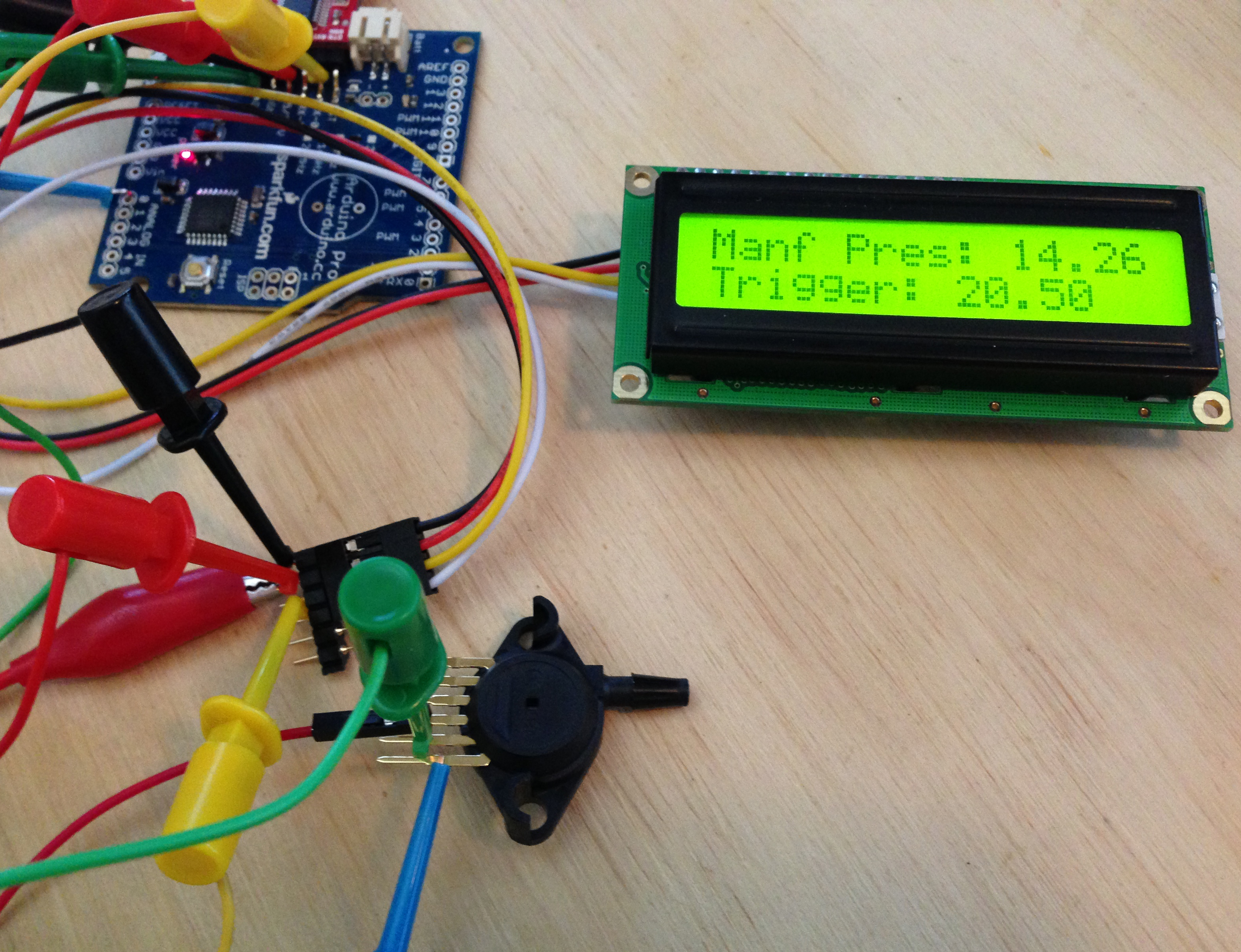
In standard turbocharger systems, there is simply a diaphragm that pops at the set pressure, and allows air to flow into the wastegate, reducing the amount of flow through the turbine, thus lowering the output pressure of the compressor. In the audi, there is a valve called the N75 with a two-conductor cable and 3 hoses connected to it: the turbo compressor tap, the wastegate input, and the airbox (for clean air feed under vacuum). I assumed this was simply a solenoid valve, and energizing it causes it to open. As such, my first code revision simply emulated a manual boost controller: at the set pressure (controlled by potentiometer), energize the valve and open the wastegate.

I hacked this all into the car in an evening with an arduino and an N-channel MOSFET (I KNEW that cat5 I ran into the engine compartment would come in handy...) and went for a spin. The results were... unexpected. The car drove just like it did normally and my manifold pressure gauge didn't register anything abnormal, except for one blip where the car unexpectedly made insane power while I was turning a corner. Hmmm.

I plugged the N75 back into the ECU and put my scope on it. Ah! It was being PWM'd!
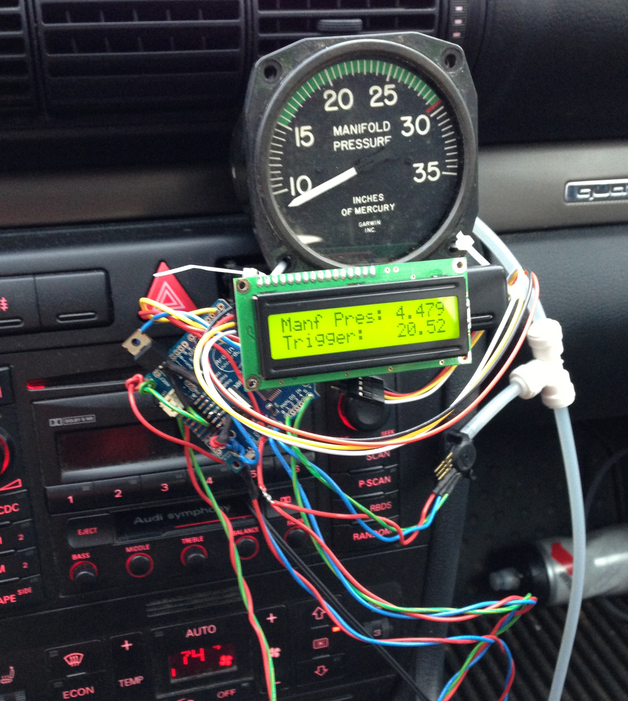
It turns out the the N75 is actually a spring-controlled valve that begins releasing air at it's set pressure of 8psi over ambient. However, the solenoid coil in it can be pushed in either direction to lower or raise the setpoint. So, my logic was backwards: in order to make more boost, you energize the coil to push against the spring. I adjusted my code to PWM the coil, pushing hardest just above 8psi boost then tapering off to the setpoint for a smooth transition. It works great! The car makes significantly more power running 20psi of boost.
The only issue with that setup was the placement of my pressure transducer: I connected it to the tap from the intake manifold, post-throttle. This means that the turbo can be ramming out 30psi, but if the throttle is closed we still see vacuum. This wouldn't be a huge issue, except that the ECU's manifold pressure sensor is located pre-throttle, and it (a) sets the mixture and (b) cuts the injectors if it sees a dangerous level of boost (about 22psi). Whenever I would sharply accelerate or take my foot off the gas, the resulting spike from the throttle movement would send the pre-throttle pressure over that limit and cause the injectors to cut then surge back - not very great.
I have the system out of the car at the moment to install up front with the new pressure transducer placement just after the turbo. Should be splendid.
In standard turbocharger systems, there is simply a diaphragm that pops at the set pressure, and allows air to flow into the wastegate, reducing the amount of flow through the turbine, thus lowering the output pressure of the compressor. In the audi, there is a valve called the N75 with a two-conductor cable and 3 hoses connected to it: the turbo compressor tap, the wastegate input, and the airbox (for clean air feed under vacuum). I assumed this was simply a solenoid valve, and energizing it causes it to open. As such, my first code revision simply emulated a manual boost controller: at the set pressure (controlled by potentiometer), energize the valve and open the wastegate.
I hacked this all into the car in an evening with an arduino and an N-channel MOSFET (I KNEW that cat5 I ran into the engine compartment would come in handy...) and went for a spin. The results were... unexpected. The car drove just like it did normally and my manifold pressure gauge didn't register anything abnormal, except for one blip where the car unexpectedly made insane power while I was turning a corner. Hmmm.
I plugged the N75 back into the ECU and put my scope on it. Ah! It was being PWM'd!
It turns out the the N75 is actually a spring-controlled valve that begins releasing air at it's set pressure of 8psi over ambient. However, the solenoid coil in it can be pushed in either direction to lower or raise the setpoint. So, my logic was backwards: in order to make more boost, you energize the coil to push against the spring. I adjusted my code to PWM the coil, pushing hardest just above 8psi boost then tapering off to the setpoint for a smooth transition. It works great! The car makes significantly more power running 20psi of boost.
The only issue with that setup was the placement of my pressure transducer: I connected it to the tap from the intake manifold, post-throttle. This means that the turbo can be ramming out 30psi, but if the throttle is closed we still see vacuum. This wouldn't be a huge issue, except that the ECU's manifold pressure sensor is located pre-throttle, and it (a) sets the mixture and (b) cuts the injectors if it sees a dangerous level of boost (about 22psi). Whenever I would sharply accelerate or take my foot off the gas, the resulting spike from the throttle movement would send the pre-throttle pressure over that limit and cause the injectors to cut then surge back - not very great.
I have the system out of the car at the moment to install up front with the new pressure transducer placement just after the turbo. Should be splendid.
Wednesday, October 24. 2012
FSK Demod and Clock Recovery
Wednesday, September 5. 2012
Embedded WiFi with an RN-XV
I picked up an RN-XV from Sparkfun to see what it would do. I didn't read the docs before I ordered, and I expected to be reading and writing registers and building my own packets. However, I was almost disappointed to learn how much functionality is supported within and how easy it is to get working.
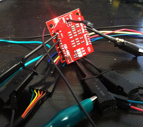
The RN-XV is a carrier board for Roving Networks' RN-171 WiFi module. Since the XV is meant to be pin compatible with the Xbees which use an odd pin spacing, I also ordered an Xbee Explorer Regulated to make connections and power easy (the FTDI cables I have are logic 3.3v but 5v Vcc, so the regulator is needed).
I plugged TX to Din, RX to Dout, added power, and BAM! Blinky lights!
WiFly Ver 2.32, 02-13-2012 on RN-171
MAC Addr=00:06:66:72:20:58
Auto-Assoc roving1 chan=0 mode=NONE FAILED
Unfortunately, it didn't respond to my serial input. After a bunch of tracing and reading, it turns out that the Xbee board does logic level shifting with diodes. The Xbees's have pullup resistors in their Din pins, however the RN modules do not. After adding a 10k resistor from Vcc to Din, I was able to link it to my network and ping things first try.
CMD
<2.32> set wlan phrase myWifiPasswd
AOK
<2.32> join mySSID
Auto-Assoc secure chan=11 mode=WPA1 SCAN OK
Joining mySSID now..
<2.32> Associated!
DHCP: Start
DHCP in 775ms, lease=86400s
IF=UP
DHCP=ON
IP=192.168.9.61:2000
NM=255.255.255.0
GW=192.168.9.1
Listen on 2000
ping 4.2.2.1
Ping try 4.2.2.1
<2.32> 64 bytes from 4.2.2.1: seq=1 ttl=251 time=6.56 ms
64 bytes from 4.2.2.1: seq=2 ttl=251 time=6.41 ms
<2.32>
With the default settings, you can open a socket to the device via wifi on port 2000. Any data that arrives goes out the serial, and any data in the serial goes out the socket. Easy as pie. Now I just need to find something cool to do with it...
For the curious: RN-XV Datasheet (pinout), RN-171 Manual and Command Set
Thursday, August 9. 2012
Flying Home
Saturday, May 5. 2012
Hybrid Rockets: v2
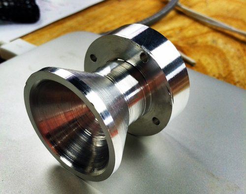
Inspired by the wild success of the previous rocket engines, I machined some cases and nozzles from aluminium to see what would happen. What happened was exactly what was expected: epic thrust, followed shortly by epic structural failure.
I machined this beautiful nozzle on the lathe and was extremly proud of it. I knew that, being aluminium, it wouldn't last more than a few seconds assuming ignition was acheived, but it sure was awesome until that point.
And lo, it failed just like expected (through the thin parts), but not before making an absolutely epic flame plume and a noise I can't quite describe other than LOUD. But check out that ablation!
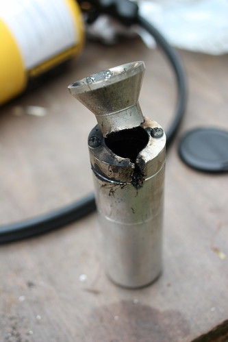
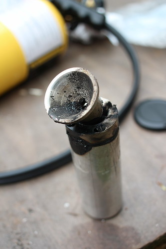
Since we still had fuels but no more nozzles nor cases, we decided we better burn through a few more home depot plumbing engines. We succeeded wildly at this goal as well.

After that was through, we realized we had the new o2 regulator that might make the 10' black iron 'engines' work a bit better. With much haste, the motor was connected and ignited.


Unfortunately I didn't get any pictures of the actual firing as I was hiding behind the most dense objects I could find, in this case the o2 tanks. Suffice to say the cloud of deathgas was too thick to see through and expansive enough to cover an airport. Great success! We still only got about 1' of the PVC burning, we're going to step up to either multiple o2 injectors, or liquid o2.
I machined this beautiful nozzle on the lathe and was extremly proud of it. I knew that, being aluminium, it wouldn't last more than a few seconds assuming ignition was acheived, but it sure was awesome until that point.

And lo, it failed just like expected (through the thin parts), but not before making an absolutely epic flame plume and a noise I can't quite describe other than LOUD. But check out that ablation!
Since we still had fuels but no more nozzles nor cases, we decided we better burn through a few more home depot plumbing engines. We succeeded wildly at this goal as well.
After that was through, we realized we had the new o2 regulator that might make the 10' black iron 'engines' work a bit better. With much haste, the motor was connected and ignited.
Unfortunately I didn't get any pictures of the actual firing as I was hiding behind the most dense objects I could find, in this case the o2 tanks. Suffice to say the cloud of deathgas was too thick to see through and expansive enough to cover an airport. Great success! We still only got about 1' of the PVC burning, we're going to step up to either multiple o2 injectors, or liquid o2.
Friday, April 27. 2012
Hybrid Rockets: v1
If you've followed my blog for a while (years) you'll note I like rockets. In the more recent years there had been a significant lack of proper exothermic reactions, and this needed to change.
I started matlabbing and thinking of good ways to do liquid-propellant motors, but thought that perhaps I should attempt the more-simple hybrid rocket engines first. On a Saturday morning I hit Home Depot and purchased all the things one needs to make a simple hybrid motor: oxygen, a rubber hose or plastic stock, and enough pipe fittings to put a small hole on the end.
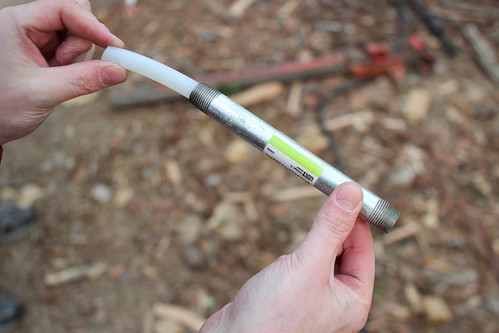
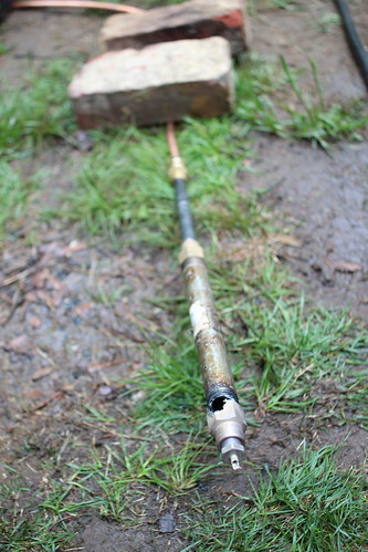
Here you can see I have some rubber hose (the fuel) inside a metal pipe. When the oxygen passes through the hose, the pair REALLY want to burn. Below, the whole setup assembled:
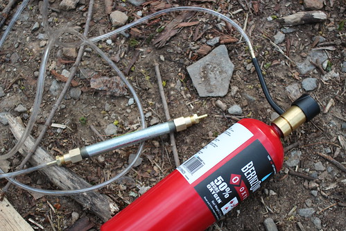
The home depot ox tank comes with a tiny regulator, which later became a problem. However the setup on a whole is extremely simple. Ignition was achieved by inserting a bit of rubber through the nozzle and touching the tube inside, flowing a small amount of ox through the system, and lighting the rubber with a torch. Worked first time!

As stated, we soon needed more oxygen. Luckily Ken had his welding setup on hand....

As you can see from Ken's face, much more mass flow happened...
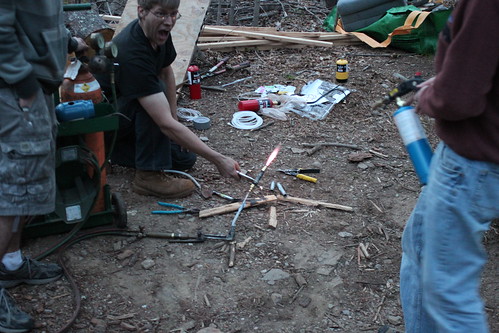
Of course, things quickly progressed from there. Ken noted he had an idea, and quickly returned with a 10' length of black iron pipe and a similar piece of PVC that fit inside. He drilled holes in two caps, threaded them on, and we were ready to roll.

Fortunately enough for us, we could only get enough oxygen flow for about 6" of PVC to burn. Regardless, that produced a TON of black deathsmoke, heat, and noise. Had we had a larger flow regulator, the thing would have killed everyone in town. We'll have to order one for next time.
I started matlabbing and thinking of good ways to do liquid-propellant motors, but thought that perhaps I should attempt the more-simple hybrid rocket engines first. On a Saturday morning I hit Home Depot and purchased all the things one needs to make a simple hybrid motor: oxygen, a rubber hose or plastic stock, and enough pipe fittings to put a small hole on the end.
Here you can see I have some rubber hose (the fuel) inside a metal pipe. When the oxygen passes through the hose, the pair REALLY want to burn. Below, the whole setup assembled:
The home depot ox tank comes with a tiny regulator, which later became a problem. However the setup on a whole is extremely simple. Ignition was achieved by inserting a bit of rubber through the nozzle and touching the tube inside, flowing a small amount of ox through the system, and lighting the rubber with a torch. Worked first time!
As stated, we soon needed more oxygen. Luckily Ken had his welding setup on hand....
As you can see from Ken's face, much more mass flow happened...
Of course, things quickly progressed from there. Ken noted he had an idea, and quickly returned with a 10' length of black iron pipe and a similar piece of PVC that fit inside. He drilled holes in two caps, threaded them on, and we were ready to roll.
Fortunately enough for us, we could only get enough oxygen flow for about 6" of PVC to burn. Regardless, that produced a TON of black deathsmoke, heat, and noise. Had we had a larger flow regulator, the thing would have killed everyone in town. We'll have to order one for next time.
Thursday, September 29. 2011
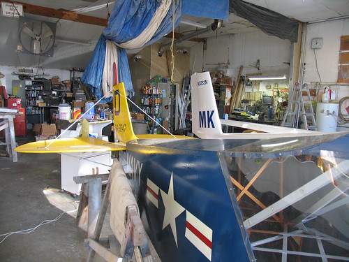
Sonerai IIL Running Happily
Saturday, February 19. 2011
Finished My PPL
Monday, October 11. 2010
Launching Ellenville
Tuesday, July 13. 2010
Landing the FP202
Tuesday, April 20. 2010
My first "real" aircraft!
The hang glider is fun, but I really wanted to fly something I could GO places with. I bought a Fischer Flying Products FP-202 ultralight on Craigslist for $2000. It was hilarious.
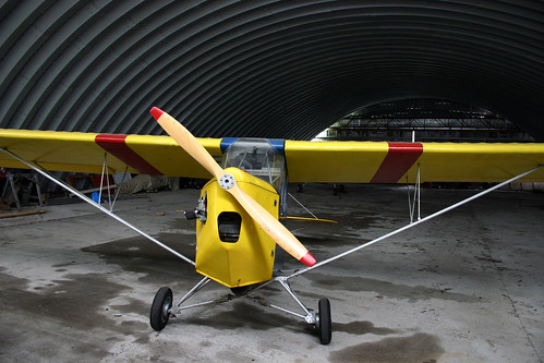
The plane had sat for a number of years in a barn. It wouldn't start without copius amounts of ether, some wood was cracked, there were some holes in the fabric. But it was mine. By spring, I had replaced the main jet in the carb as well as de-gunking everything, patched the holes, and taxied around a bit.
I lined up on the runway at 8B5, applied full power, and off I went:

I did two patterns and landed splendidly. It was epic!

I really miss that plane... I ended up selling it for $4100 to fund my private pilot's license. I'd really love to buy another one some day and drop an electric motor in it...
The plane had sat for a number of years in a barn. It wouldn't start without copius amounts of ether, some wood was cracked, there were some holes in the fabric. But it was mine. By spring, I had replaced the main jet in the carb as well as de-gunking everything, patched the holes, and taxied around a bit.
I lined up on the runway at 8B5, applied full power, and off I went:
I did two patterns and landed splendidly. It was epic!
I really miss that plane... I ended up selling it for $4100 to fund my private pilot's license. I'd really love to buy another one some day and drop an electric motor in it...
Monday, February 15. 2010
Jet Powered Hovercraft
Chris and I decided we needed to build a propane powered jet engine using a turbo from a car. Given my previous successes with hovercrafts, of course we needed to step the game up.
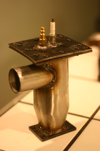
Our combustion chamber takes air from the compressor, swirls it around with liquid propane, then burns it, creating a huge expansion of the inputs. The gases then pass out into the turbine section of the turbo, spinning the compressor faster, and so on. The brass nozzle you see is the propane connection. The sparkplug is to start the combustion, but the flame is self-sustaining once it's running.
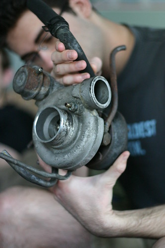
We rigged the combustion chamber to the output of the shop vac, connected the spark coils, and let a little gas flow. Much to our surprise, a significant roar was produced! We were even more pleased when the roar continued after we switched off the sparkplug. Below, Eric inspects the turbo.
When we put it all together, the unit was spinning at upwards of 120 krpm, and blasting the rhododendrons around across the yard. We also used it for snow clearing.
While we still had it running (ie before it was scavenged for parts), two exciting things happened. Once, when we drilled out the propane fittings to get more gas through. This made the engine run at a higher compression of course. Right as Ken reached across the motor to poke a gauge, the cold air manifold from the compressor separated from the combustion chamber, and the resulting gas instantly melted all the hair off Ken's arm. However perhaps more amusing was the time the bearing's oil seal failed during a full-thrust run. 60psi hot, thin motor oil sprayed into the turbine housing and instantly turned to smoke. The sheer amount of black death coming out the back of that jet engine is an image I won't soon forget. epic.
Our combustion chamber takes air from the compressor, swirls it around with liquid propane, then burns it, creating a huge expansion of the inputs. The gases then pass out into the turbine section of the turbo, spinning the compressor faster, and so on. The brass nozzle you see is the propane connection. The sparkplug is to start the combustion, but the flame is self-sustaining once it's running.
We rigged the combustion chamber to the output of the shop vac, connected the spark coils, and let a little gas flow. Much to our surprise, a significant roar was produced! We were even more pleased when the roar continued after we switched off the sparkplug. Below, Eric inspects the turbo.
When we put it all together, the unit was spinning at upwards of 120 krpm, and blasting the rhododendrons around across the yard. We also used it for snow clearing.
While we still had it running (ie before it was scavenged for parts), two exciting things happened. Once, when we drilled out the propane fittings to get more gas through. This made the engine run at a higher compression of course. Right as Ken reached across the motor to poke a gauge, the cold air manifold from the compressor separated from the combustion chamber, and the resulting gas instantly melted all the hair off Ken's arm. However perhaps more amusing was the time the bearing's oil seal failed during a full-thrust run. 60psi hot, thin motor oil sprayed into the turbine housing and instantly turned to smoke. The sheer amount of black death coming out the back of that jet engine is an image I won't soon forget. epic.
Tuesday, November 17. 2009
Hang Glider Upgrade
While fun, the hang glider I built wasn't exactly the best-flying device in the world. But it just so happened that the local hang glider pilots were amused enough at me for it that they found me a used "real" hang glider to buy for $300!

My Gemini 134 and I have flown quite a few interesting places since then, including actual hang glider launches, ski hills, beaches, and flat grass fields with a winch. I'd really like to put an electric motor on the back of the harness some day, if I can find the time...
Here's a pic of me at the practice hill in Cooperstown on a student glider:
Tuesday, August 11. 2009
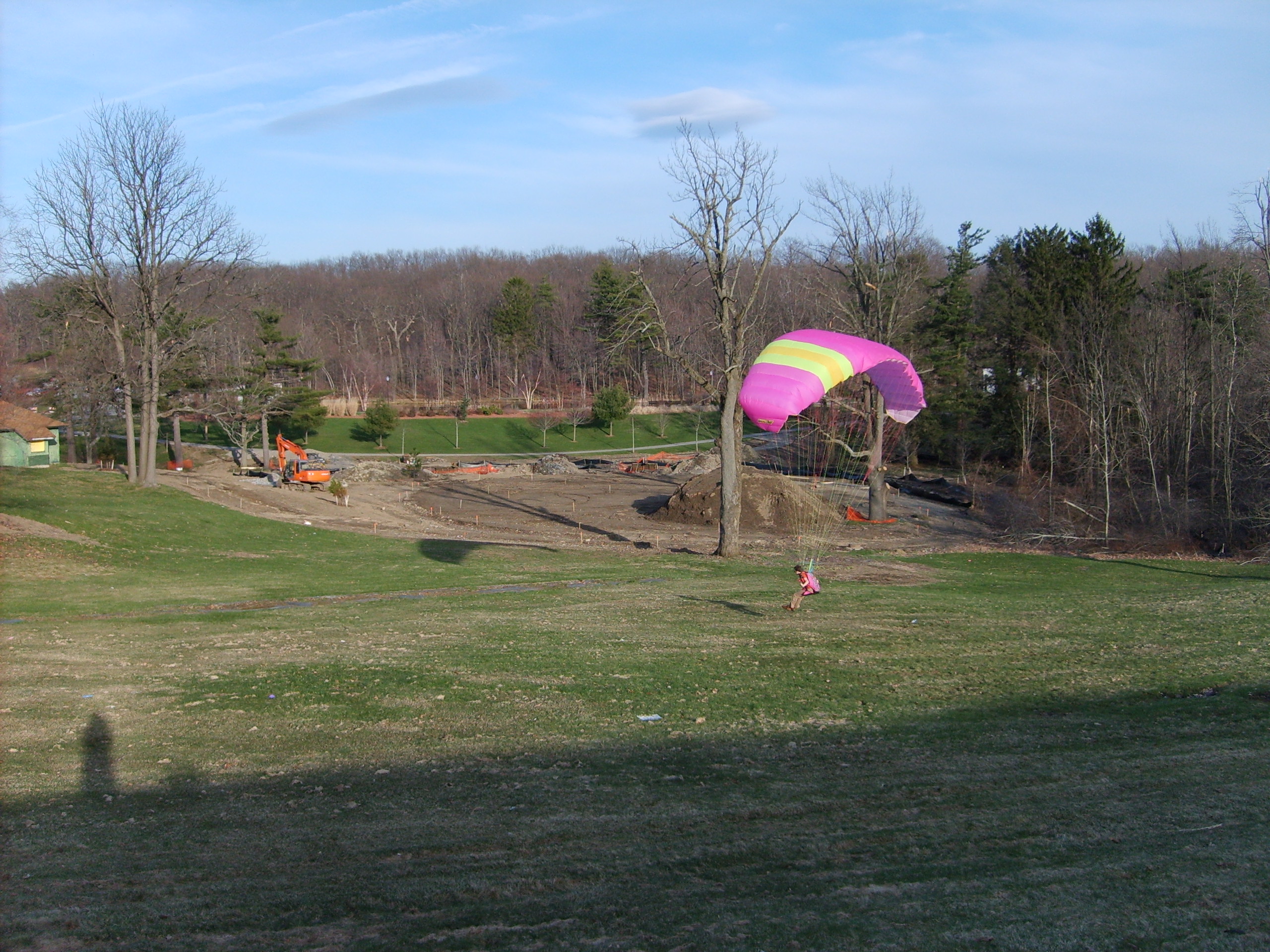
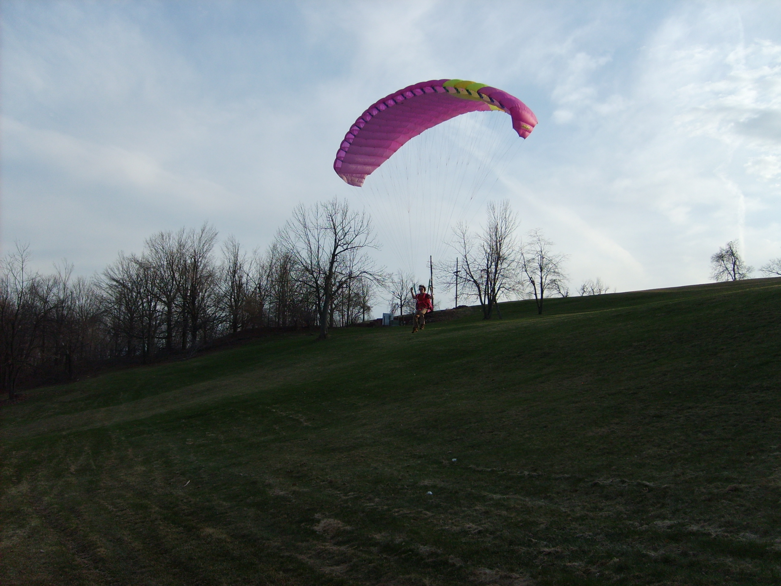
That Time I Owned a Paraglider
After the hang glider adventures, I still wanted to fly different things, but didn't yet have enough money for any sort of "real" aircraft. So I did what anyone in my position ought to: bought an old paraglider and harness on eBay for $700!
There aren't any great flying sites in central MA, but I did get some sweet local flights in down hills and with a winch I built before selling it. Certainly an enjoyable piece of fabric.


There aren't any great flying sites in central MA, but I did get some sweet local flights in down hills and with a winch I built before selling it. Certainly an enjoyable piece of fabric.


Tuesday, August 26. 2008
On Handy Type of Virtualization
Friday, August 8. 2008
All Sorts of Tunnels
Thursday, May 29. 2008
The glider works!
This picture doesn’t show it well due to the long grass, but I am in fact flying.

(I stalled right after this picture was taken, but that’s beside the point!) This isn’t even with good wind – when the wind was favorable, I flew near half way down the hill. Despite the police, high-tension power lines inducing current in the glider frame, and fussy wind, I left the ground!
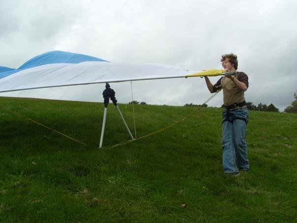

(I stalled right after this picture was taken, but that’s beside the point!) This isn’t even with good wind – when the wind was favorable, I flew near half way down the hill. Despite the police, high-tension power lines inducing current in the glider frame, and fussy wind, I left the ground!
Email me:
jack {@} crepinc.com
Recent Projects:
Analog HF Transmitter
Audi ECU Reverse Engineering
Dual DAC QAM Modulator
FPGA QAM Modulator
Geiger Counter
Gyro-Stabilized DSLR Platform
Hybrid Rocket Engines
Turbocharger Controller
WWVB Rx and Tx
Older Projects:
Balancing Bot
Capacitor Array
CNC Mill
DCIR Renderer
Electric Gokart
Hovercraft
Low Alt. Temp. Model
Shopping Cart Locker
Trebuchet
My Twitter occasionally shows projects I'm working on.
My GitHub has code from a few projects on it.